ioGlow: Webinterface enabled neopixel string
We have been busy at the Fablab pushing the boundaries of the ESP8266 platform. For this, we have made a web interface in which you can control the different preprogrammed light patterns on the chip. The system is 100% embedded in the microcontroller. All you need to do is to upload the software. It will then create a wifi-hotspot. When you connect to the hotspot, a captive portal will appear with buttons and sliders. Further, you can configure it to connect to your normal wifi network and then access it through a web browser.
The purpose of ioGlow is to give a simple platform to learn to program with. We have taken care of all the complicated stuff. This way you only have to focus on programming fun color patterns and making a nice enclosure.
See a short demo here:
Short technical description of the internal system
The code on the Wemos controller starts a SoftAP (Access Point), a webserver, websocket server and a DNS server. Any requests to the DNS server redirects to the webpage/ip which the web-server hosts. The web server transfers an HTML page to the browser. The page creates a websocket connect back to the websocket server. When the user presses a button on the HTML page, javascript thus makes a websocket call to the server that a specific button has been pressed. This is registered in a variable that defines which pattern to run at any given moment.
Materials
- Neopixel string (be aware that there is a limit to the current that you can pull directly from a Wemos/NodeMcu - in our experience one 1 meter in which you do not run at full white is a pragmatic length).
- Wemos or NodeMCU controller.
- Micro USB cable.
Wiring (Correct way)
Warning: This way of wiring limits your length of Neopixels to about 30 LEDS. The problem is that the serial chip will drop out if too much current is used for the LEDS. If you have a steady soldering hand we recommend the hack below.
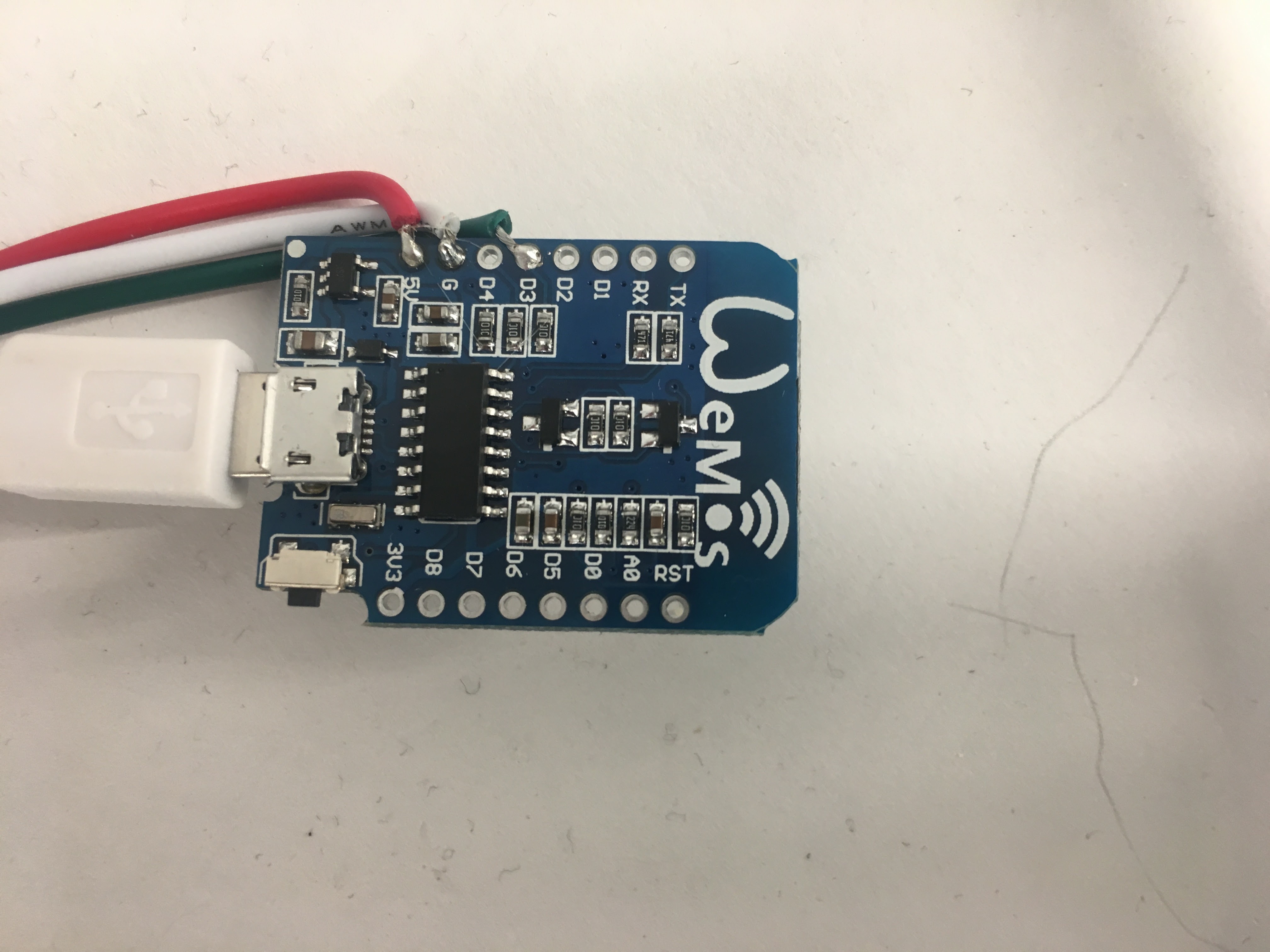
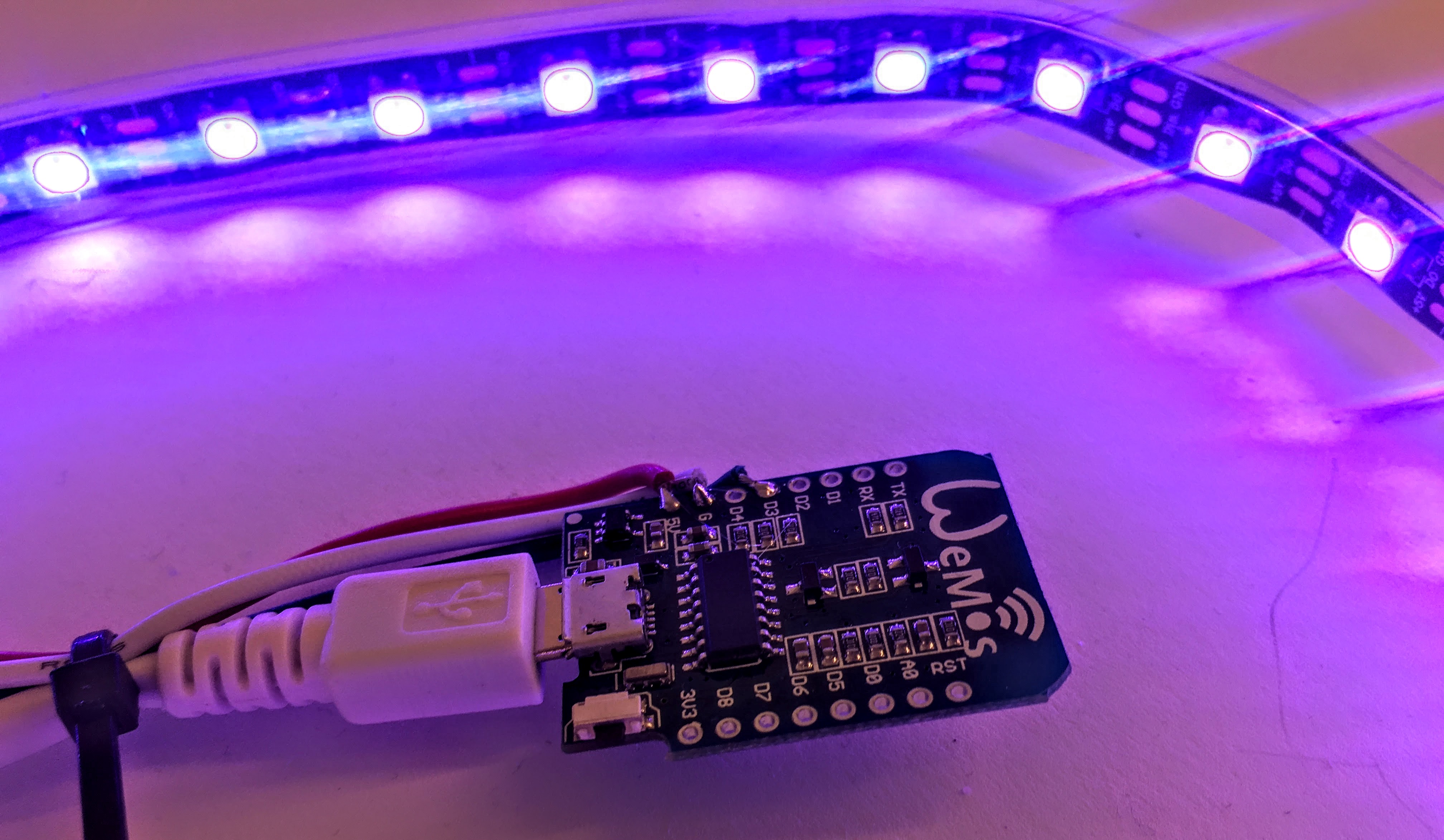
You need to solder three wires from the wemos board to the Neopixel string. Connect 5v to v5, Di to D2 on the board and G to G. Some Neopixels have two data pads DI BI. Solder both to D2.
Important - In the image we use D3. It turns out that D3 is a part of the boot process and it can create interference with firmware upload and bootup in general. D2 Seems stable.
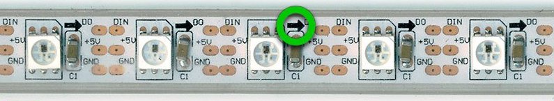
Make sure the direction on the neopixel string is correct:
Wiring (The hack)
To get more power out of the USB port we can bypass the diode sitting between 5v pin hole and the USB connector. This can be done by soldering the 5V wire from the Neopixel to the end of the diode. See image below:
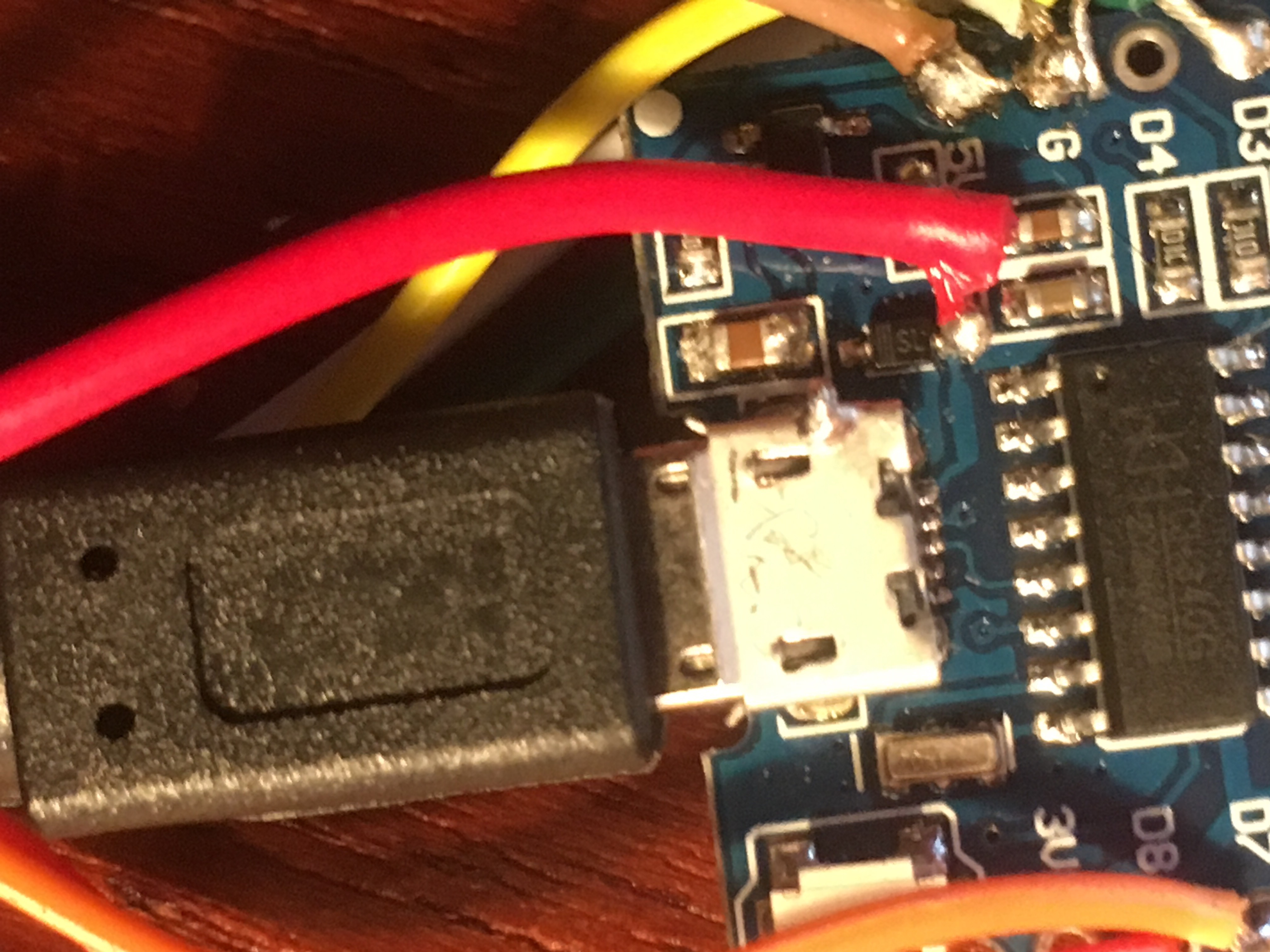
This will allow you to run about a meter at 66% full white before the Serial chip drops out. This is plenty for most use scenarios.
How to solder neopixels:
- Make sure the soldering iron is warm.
- Add a tiny bit of solder on the pads on the strip.
- Add solder on the wire.
- Put the wire to the pad and heat with the soldering iron.
See this video:
Setup
USB Serial driver
To be able to communicate with the Wemos board you will need to install the Serial drivers. On the following link you can find the latest driver:
https://wiki.wemos.cc/downloads
If you have trouble with the MAC driver you can find a later version here that is signed:
https://blog.sengotta.net/signed-mac-os-driver-for-winchiphead-ch340-serial-bridge/
Directly from the manufacturer of the Serial chip:
http://www.wch.cn/download/CH341SER_ZIP.html
Install Arduino
Download Arduino ide from here wwww.arduino.cc -> Download -> Arduino IDE (not Online ide).
!IMPORTANT! Latest version of Arduino causes problems use 1.8.3.
Install ESP8266 Board specifications
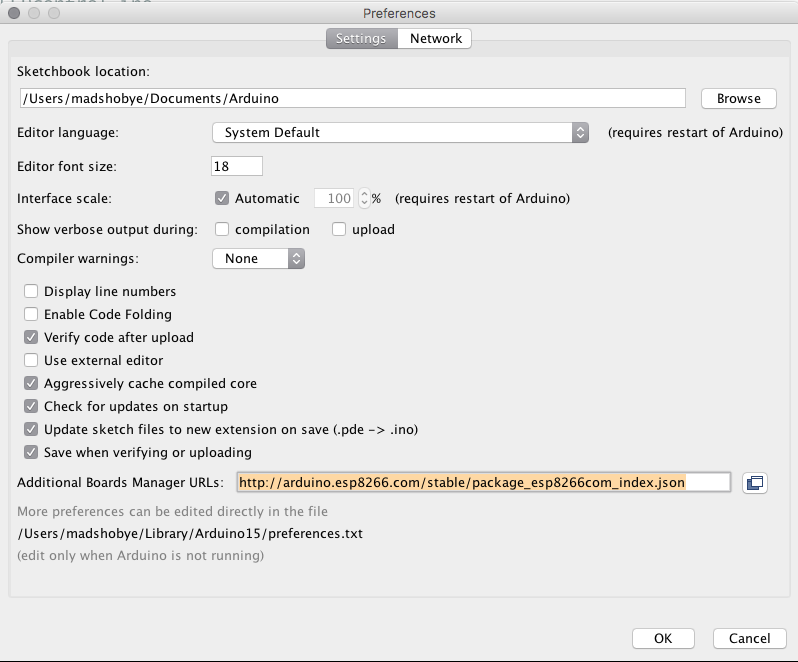
Start Arduino and open Preferences window (Arduino or Files -> Preferences).
Enter the following line into Additional Board Manager URLs field:
http://arduino.esp8266.com/stable/package_esp8266com_index.json
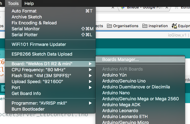
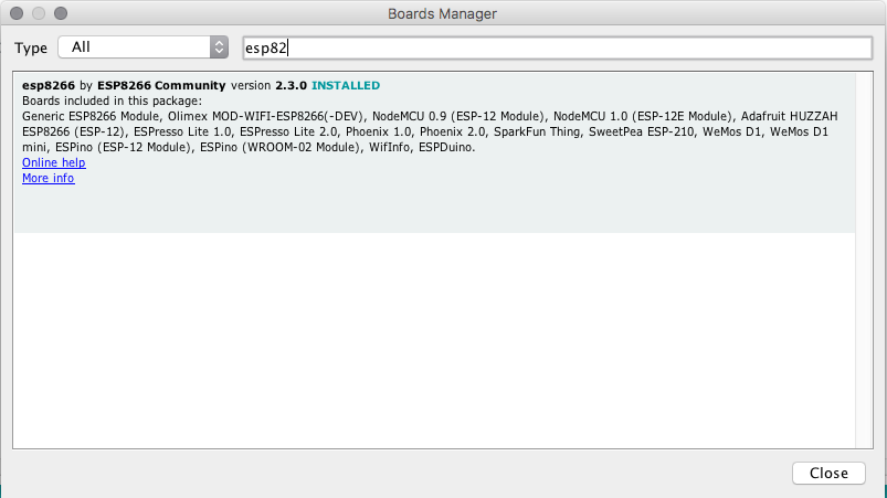
Open Boards Manager from Tools > Board menu and install esp8266 platform (and don't forget to select your ESP8266 board from Tools > Board menu after installation).
See more info here.
!important use version 2.4.0 because it works with the captive portal part of ioGlow
Install FastLED
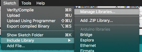
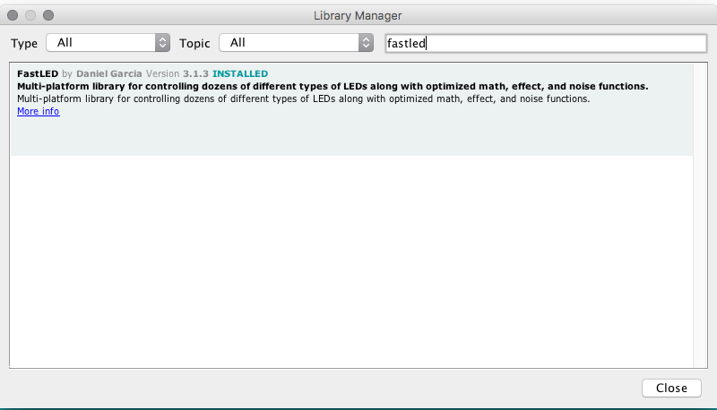
Open the sketch menu choose Manage Libraries and search for FastLED. Press install.
Install WebSocket
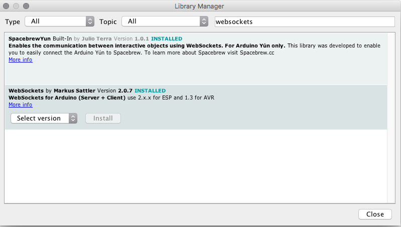
Open the sketch menu -> "include Library" -> choose "Manage Libraries" and search for WebSockets. Press install.
Upload code
Download the code here.
Use the version with the highest number.
IMPORTANT FOR WINDOWS USERS: The files consist of a bunch of INO files. The ino files have to be in a folder named after the IOGLOW version. Thus if it is version one, then the folder should be named "ioGlowv1.ino". Please verify that this is the case before opening it in Arduino. To open in arduino double click on "ioGlowv1.ino". IT IS IMPORTANT TO UNZIP THE FILE (Right click and press extract to folder or something like that).
When opened you should have a window that looks like this:
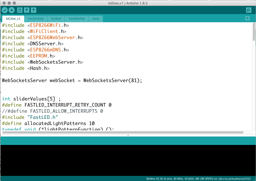
Notice the five tabs (ioGlow_v1, credentials, fastled, handleHTTP, tools). If they are not present, then you did not verify that the foldername was consistent with the main file.
If you are in a classroom with multiple ioGlows then you can change the wifi name to something else so you can identify your Wemos:
String name = "ioGlow-";
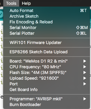
Select the board "Wemos D1 R2 & mini" in the tools menu.
Press compile (the V icon in the top left corner) to verify that you have installed the code properly. If you installed everything correctly, you should get a "Done compiling" below the code.
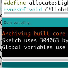
When you compile the sketch, you will get some warnings in red at the bottom of the arduino window: "No hardware SPI pins defined", warning: "serialportsetbaudrate: baud rate 921600 may not work" etc. This is normal, don't worry.
Plug in the USB cable connected to the Wemos board and configure the Arduino to upload to the correct port. For Windows, it will be the highest port number e.g. com6. For Mac, it will be named something like "/dev/etc/cu.wch...".
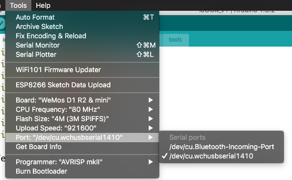
While you are at it, you can also change the upload speed to "921600". It will make the upload significantly quicker.
Now press upload on the button with a left-pointing-arrow icon on the top left corner of the window.
If everything succeeds, you will get a "Done upload" message below the code part of the window.
Using the web interface
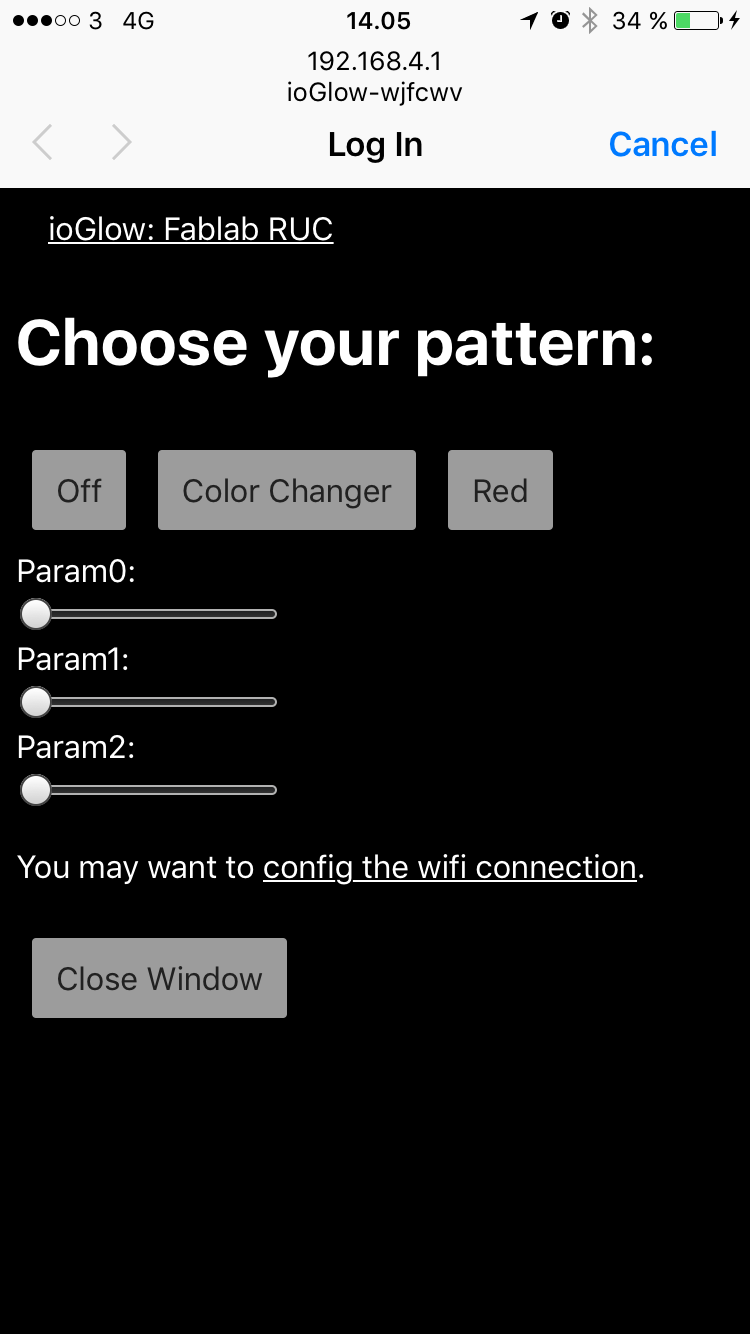
Open wifi settings on your phone. Find the wifi name oiGlow-xxxxxx. An individual name is created for each Wemos board (to prevent overlapping wifi names in classroom environments). Pick the wifi and wait a few seconds. A portal should pop up with the interface. In this interface, you can also define which wifi it should connect to. If you want to get the interface which connected to your normal network you can go to the url http://oiGlow-xxxxxx.local. Remember to change the x's to the name of you specific devices wifi name.
Start programming patterns for the neopixels
Neopixels are versatile light strings where each diode can be controlled individually. Each one has Red, Green, and Blue and can be from 0 to 255 in brightness. Multiple libraries exists to use noepixels. We use Fastled in this case.
In the code each light pattern has its own method to define the light pattern. E.g. to make every pixel red the following code will do it:
void red() {
  for (int i = 0; i < NUM_LEDS; i++)
  {
    leds[i] = CRGB(255, 0, 0);
    yield();
  }
}
The code runs through every pixel and sets the color to RGB 255,0,0. Which means the full brightness of the red channel and turning the green and blue off.
IMPORTANT: Setting all channels to FULL white e.g. CRGB(255, 255, 255) might fry the Wemos board because it draws too much current.
Adding your own pattern
Let's say that we want a Disco pattern. In the setup method we would need to add a line that would add the disco pattern to the possible list of patterns:
addLightPattern(disco, "Disco");
Further, we would need to add a method that the controller can call when the disco pattern has been selected in the webinterface:
void disco()
{

}
Let's say that your disco is the most simple pattern possible. We simply want one diode to be red. Then this command (inserted between the two curly brackets would do it):
leds[0] = CRGB(255, 0, 0);
If we want the three first leds to be red. We can copy the line and change the index number:
 leds[0] = CRGB(255, 0, 0);
 leds[1] = CRGB(255, 0, 0);
 leds[2] = CRGB(255, 0, 0);
As you might already realize this strategy quickly becomes redundant, thus, we use the for loop to run through them all:
  for (int i = 0; i < NUM_LEDS; i++)
  {
    leds[i] = CRGB(255, 0, 0);
    yield();
  }
For now, we have only made a red pattern. A simple way to make blinky disco is to add some randomness to the mix:
  for (int i = 0; i < NUM_LEDS; i++)
  {
    leds[i] = CHSV(random(0,255), 125, 125);
    yield();
  }
Notice how we also changed the color mapping to HSV instead of RGB. In the HSV color mode, the first parameter is the color, the second the saturation, the third the brightness.
Getting the values from the sliders in the webinterface
The webinterface has 3 generic sliders that you can use to allow the user to control things like color, speed etc. in real-time.
The three sliders can be accessed through sliderValues[0], sliderValues[1], and sliderValues[2]. The values of the sliders goes from 0 to 255.
Advanced color patterns: Take a look at the Reference
https://github.com/FastLED/FastLED/wiki/Pixel-reference
Adding an ultrasonic sensor
The sketch includes time for an HC-SR04 ultrasonic distance sensor.
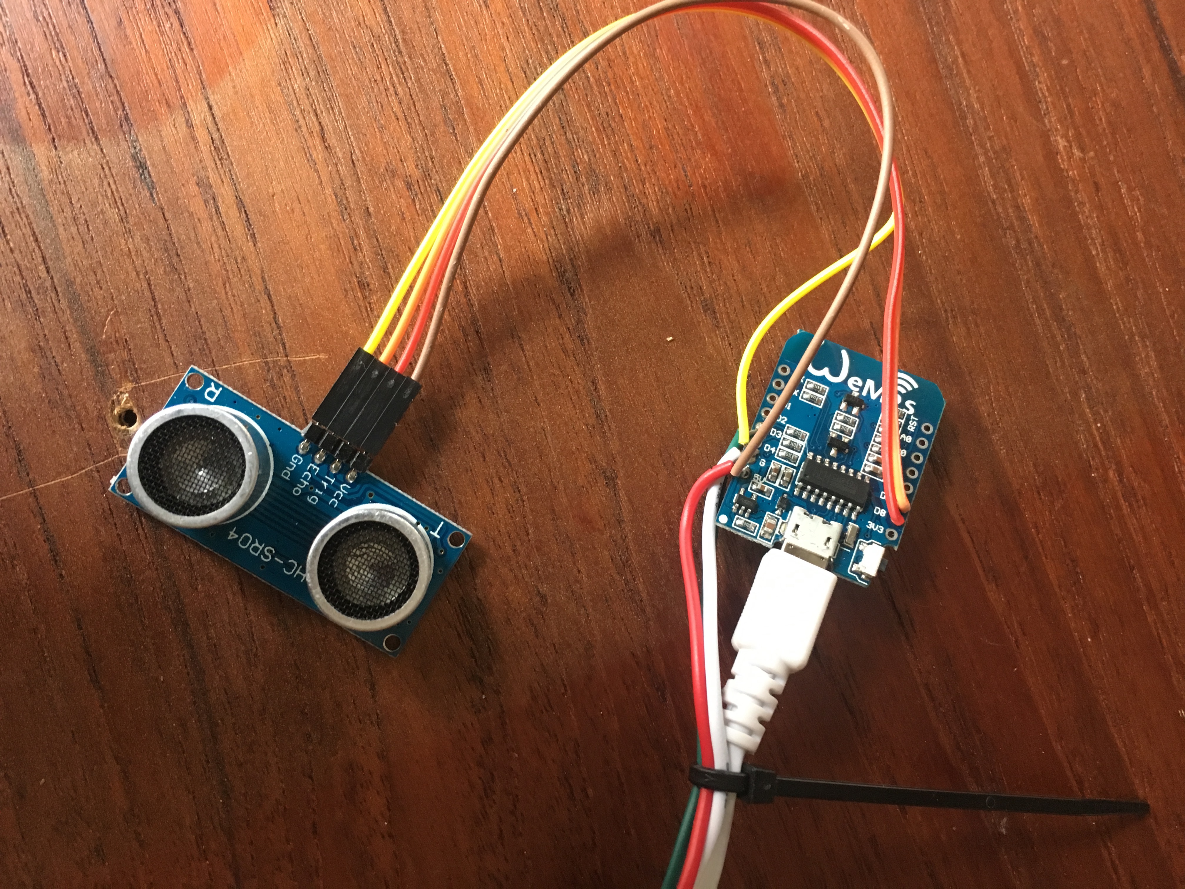
Solder Trig to D8, Echo to D7, Ground to Ground and VCC to 5V.
To enable the code to run with the Ultrasonic sensor change the 0 in the following line to 1.
#define ULTRASONIC 0
An interactive button will appear in your sketch. The code for the interactive button looks like this:
void interactive()
{
  if (ULTRASONIC)
  {
    float value = usRead();
    int valueMapped = constrain(map(value, 0,200,255,0),0,255);
    //Serial.println(value);

    for (int i = 0; i < NUM_LEDS; i++)
    {
      leds[i] = CRGB(valueMapped, 0, 0);
      yield();
    }
  }

}
Notice that the different type of range between the sensor and the colors requires us to map the range between them. The ultrasonic may sometimes return a larger value than the range so it is further necessary to constrain the value between 0 and 255.
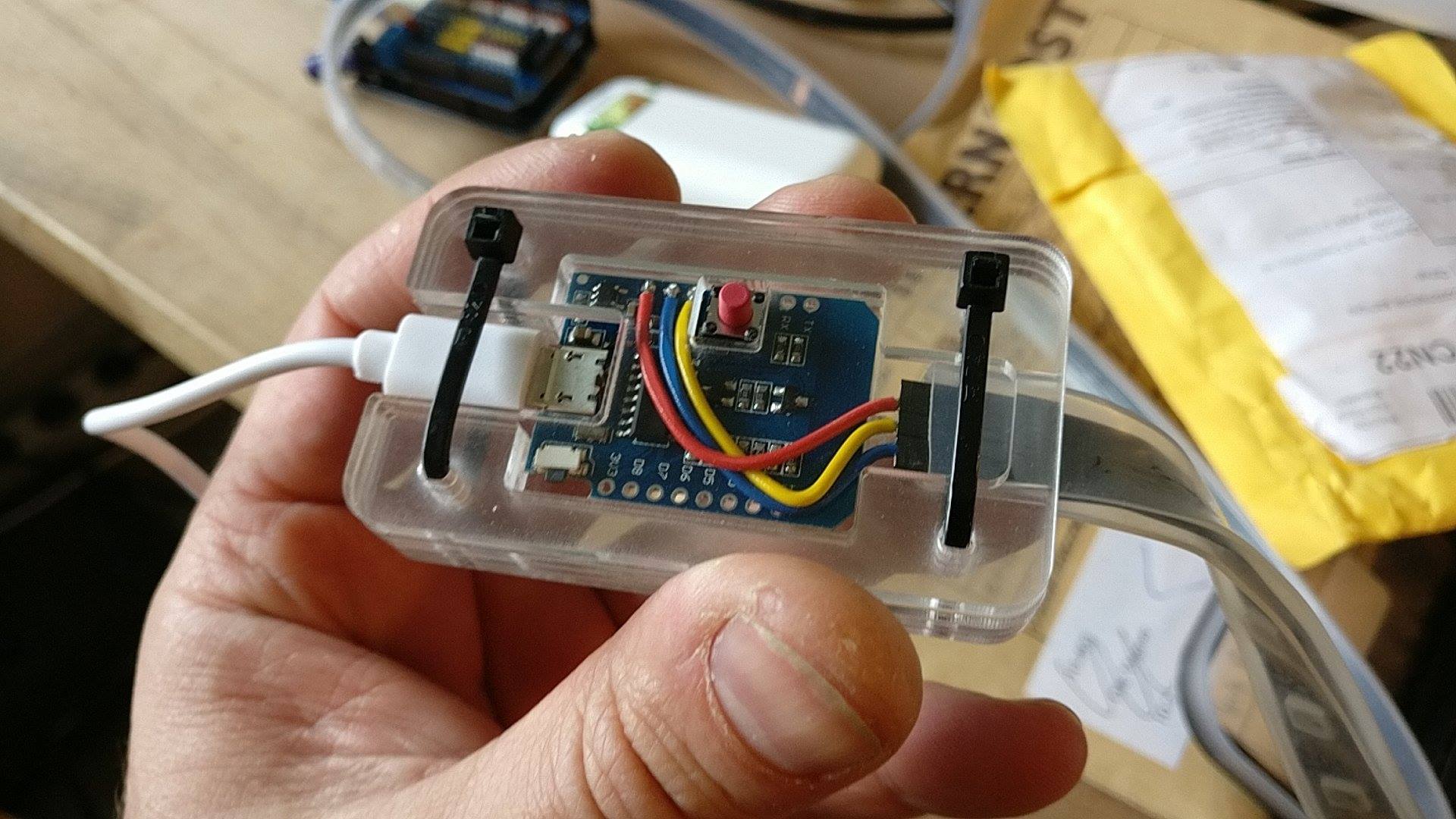
Enclosure
Included with the download of the Arduino code is a nice laser cutting friendly enclosure to pack the wemos into.
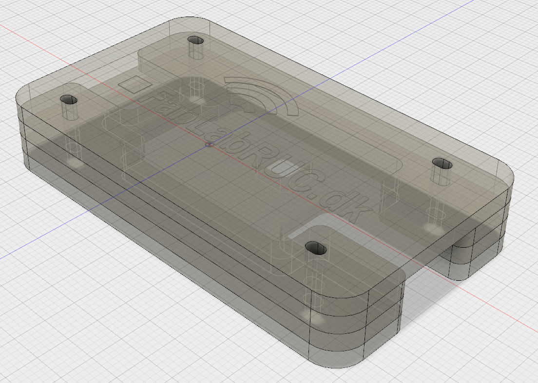
Use zip ties to clamp the layers together: