ESP32 setup guide
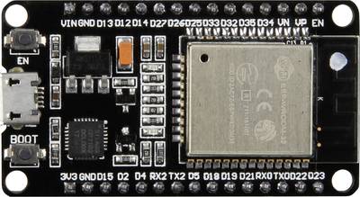
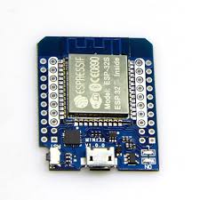
This guide is only about how to setup your Arduino IDE to work with the ESP32 microconetroller . The ESP32 is a low-cost microcontroller with Wifi and Bluetooth. Your computer just need a driver and Arduino IDE needs the ESP32 board managers. These are to diferent boards, but both are ESP32.
Chip driver
To use the ESP32 you need a driver:
https://www.silabs.com/products/development-tools/software/usb-to-uart-bridge-vcp-drivers
Choose your operating system, unpack the .zip file and run the installer file.
Install the ESP32 in Arduinos IDE
When you have the driver you need to install the board in Arduino IDEs board manager.
This is done like in two steps:
1. Step
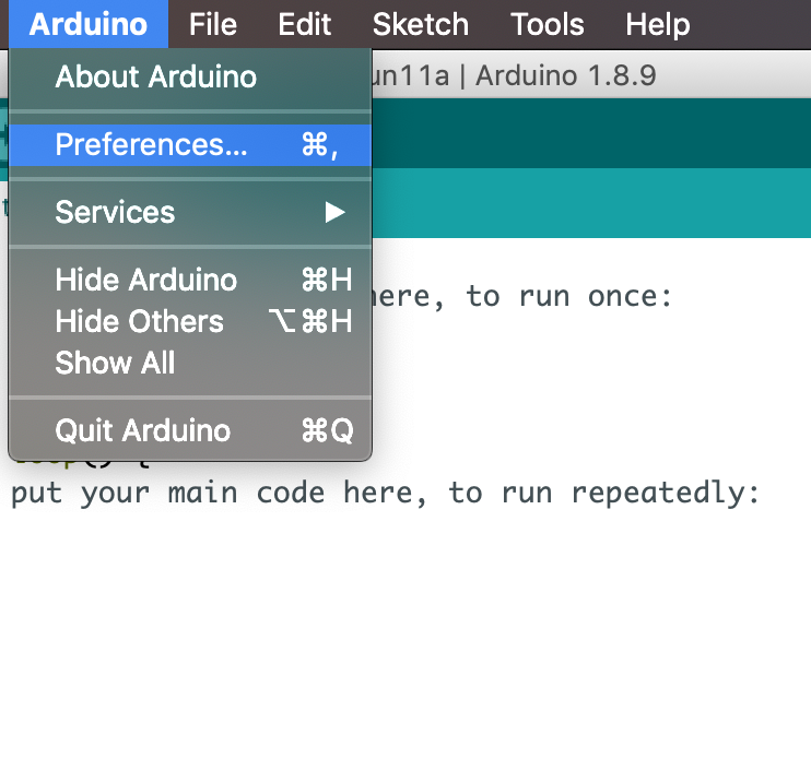
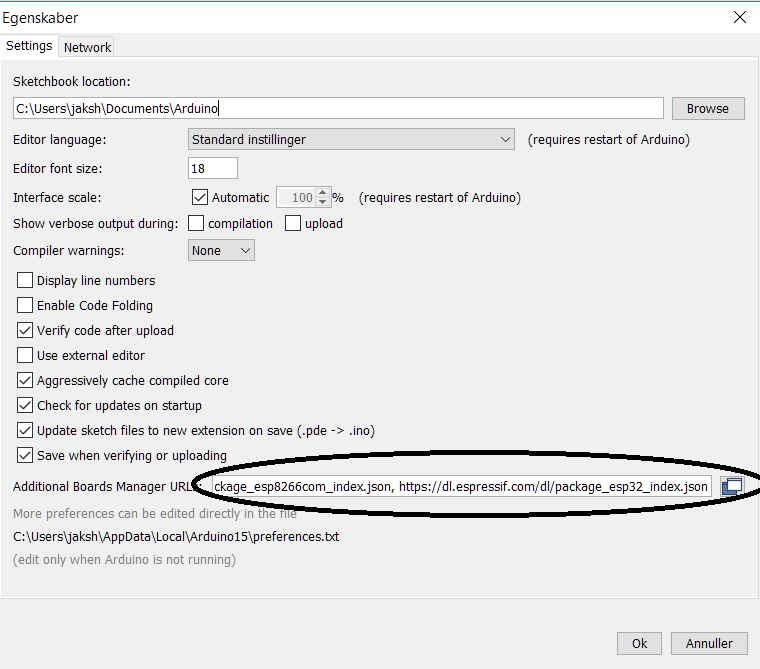
Add an URL to additional board managers
File -> Preferences
In the field additional board managers copy paste this URL:
https://dl.espressif.com/dl/package_esp32_index.json
If you already got other board managers you need to separate the URLs with a comma an a space.
2. Step
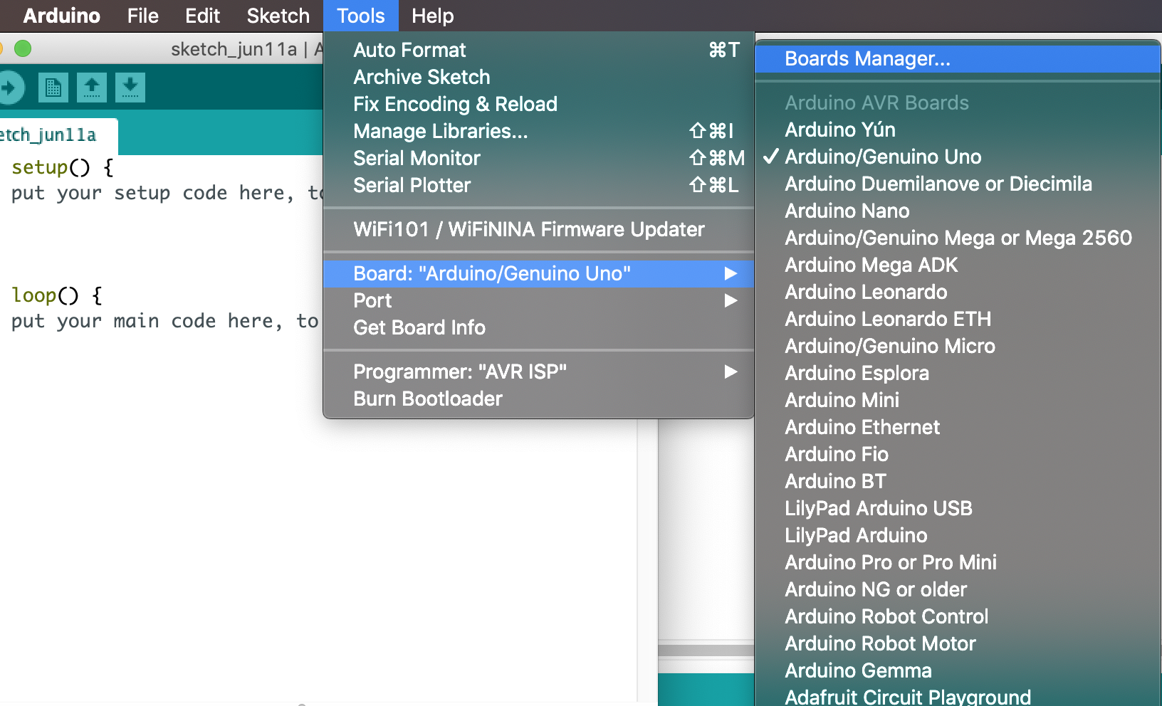
You need to download the ESP32 board to your computer.
Do this in this path:
Tools -> Board -> Boards Manager...
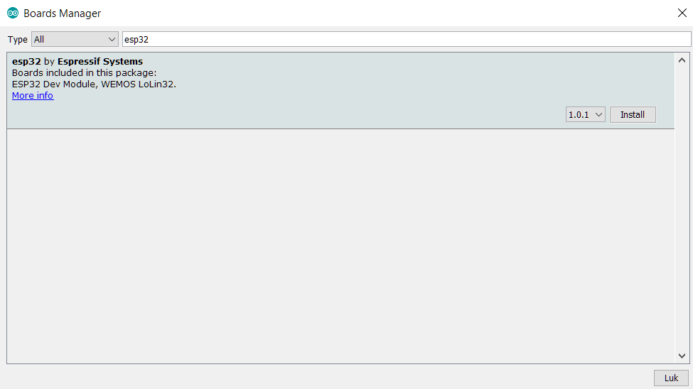
Search for ESP32. Click on esp32 by Espressif Systems.
Now click on the install button.
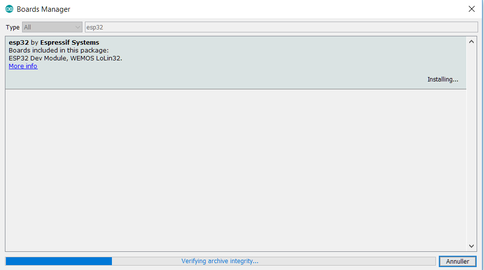
When the installation is complete it is recommended to restart Arduino IDE.
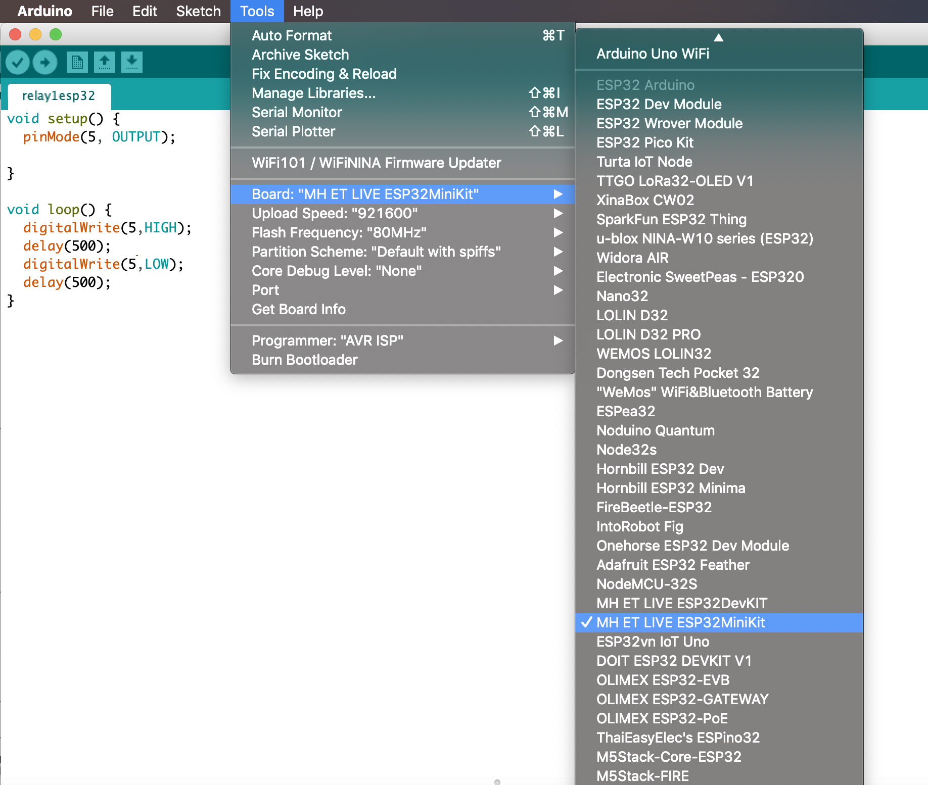
Dependent on which ESP32 board you got different versions can be selected.
When working with ESP32 mini choose MH ET LIVE ESP32mini kit
Tools -> Board
If the upload speed "921600" doesn't work try to lower the speed to "115200". You can also try to press the boot button on the ESP32 in the beginning of your upload.
A good test code is the blink example from Arduinos basic example code.
To test with this code you need a diode to be connected to Ground (GND) and digital pin 13 (D13).
/*
  Blink
  Turns on an LED on for one second, then off for one second, repeatedly.

  Most Arduinos have an on-board LED you can control. On the UNO, MEGA and ZERO
  it is attached to digital pin 13, on MKR1000 on pin 6. LED_BUILTIN is set to
  the correct LED pin independent of which board is used.
  If you want to know what pin the on-board LED is connected to on your Arduino model, check
  the Technical Specs of your board  at https://www.arduino.cc/en/Main/Products

  This example code is in the public domain.

  modified 8 May 2014
  by Scott Fitzgerald

  modified 2 Sep 2016
  by Arturo Guadalupi

  modified 8 Sep 2016
  by Colby Newman
*/

 #define LED_BUILTIN 13
// the setup function runs once when you press reset or power the board
void setup() {
  // initialize digital pin LED_BUILTIN as an output.
  Serial.begin(115200);
  pinMode(LED_BUILTIN, OUTPUT);
}

// the loop function runs over and over again forever
void loop() {
  digitalWrite(LED_BUILTIN, HIGH);   // turn the LED on (HIGH is the voltage level)
  delay(1000);
  digitalWrite(LED_BUILTIN, LOW);    // turn the LED off by making the voltage LOW
  delay(1000);
  // wait for a second
}
If you got the diode to blink you are ready to do more advanced stuff with the ESP32.
We are working on a guide to communicate wireless between ESP32 boards with a MQTT-library.