Ecosystem Interaction Kit
In this page you will find help and guidance for the electronics and programming part of the summer course on Biofabbing & Ecology at FabLab RUC.
Other resources:
At the FabLab we have collected the most common programming patterns
You can also find more info and references to arduino coding language at the arduino website.
Index
BME680 temperature, humidity and VOC gas sensor
Relay - electrically operated switch & motors
ESP32 Intro
The board we use is the MH-ET LIVE ESP32 Mini kit. Here you can find information about the MH-ET-LIVE Board, and an instructables with ESP32 examples (though using another bord). You can search and ask questions in the ESP32 Arduino Forum
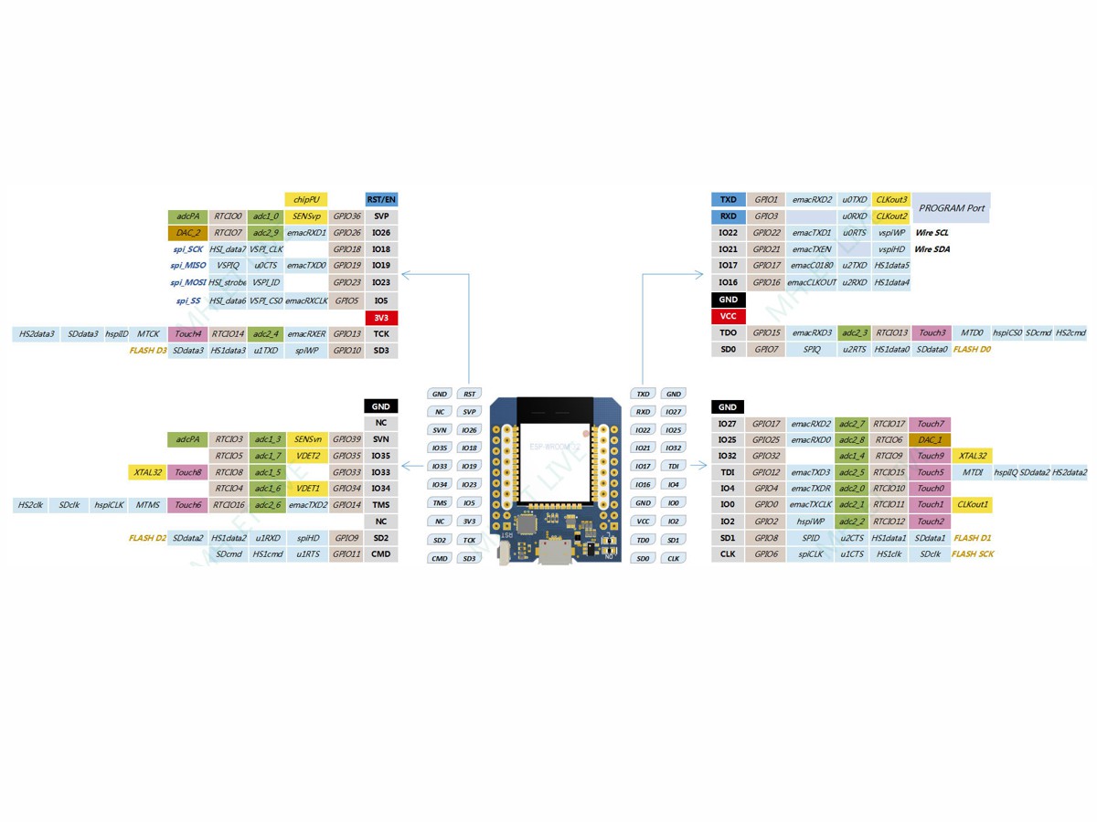
Special info and settings for ESP32 compared to normal Arduino:
When you open the Arduino IDE for the first time, you will note that the default upload speed is 921,600 bauds. This can provoque instability. Change it to 115,200 bauds.
The "LED_BUILTIN" code doesn't work. use pin "2" instead
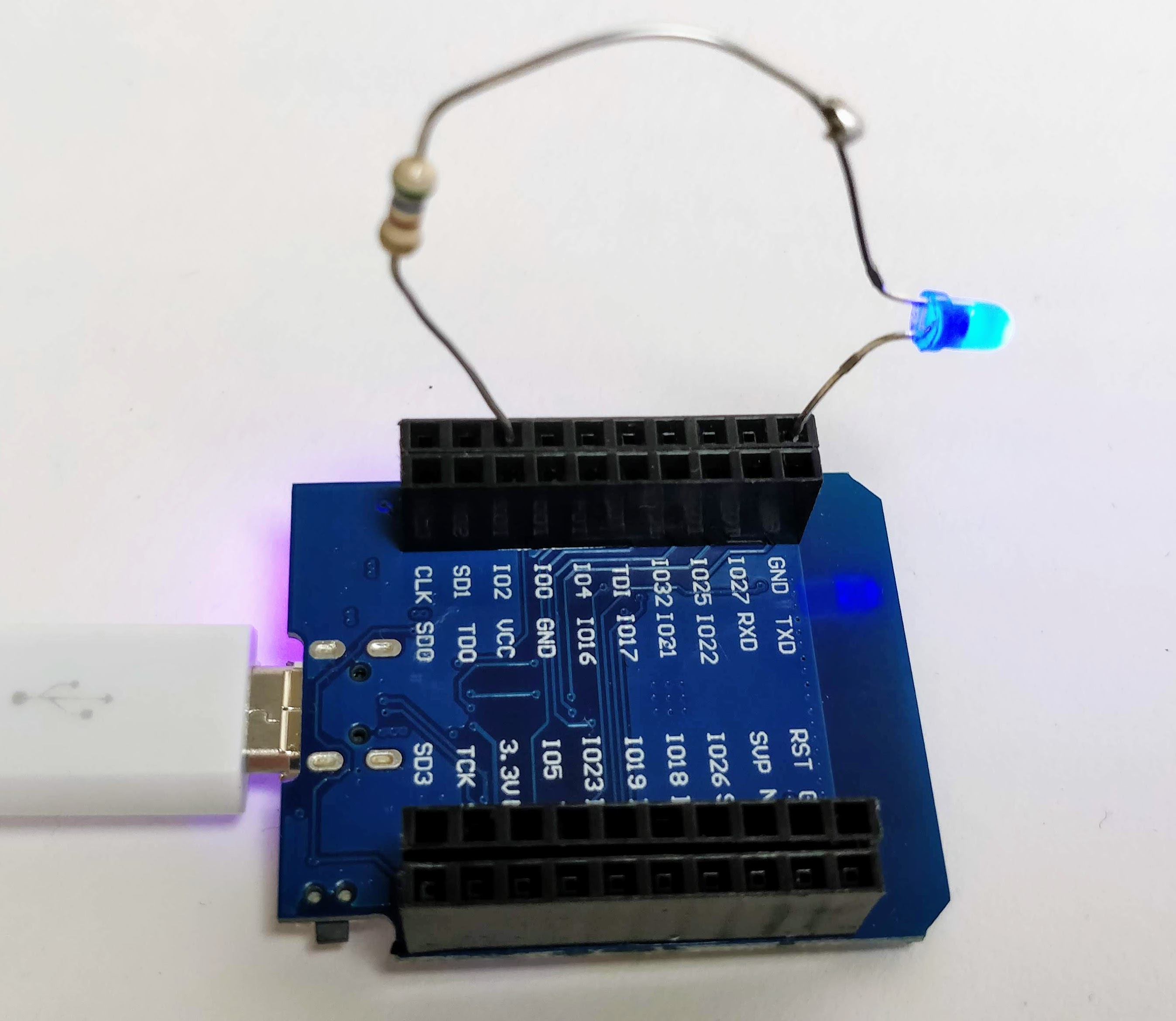
Blink
Get the onboard LED at Pin 2 to blink
/*
  ESP 32 Blink
  Turns on an LED on for one second, then off for one second, repeatedly.
  The ESP32 has an internal blue LED at D2 (GPIO 02)
*/

int LED_BUILTIN = 2;

void setup()
{
  pinMode(LED_BUILTIN, OUTPUT);
}

void loop()
{
  digitalWrite(LED_BUILTIN, HIGH);   // turn the LED on (HIGH is the voltage level)
  delay(1000);                       // wait for a second
  digitalWrite(LED_BUILTIN, LOW);    // turn the LED off by making the voltage LOW
  delay(1000);                       // wait for a second
}
Wiring
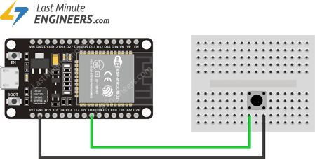
Button
Wiring
Code I
void setup()
{
    pinMode(18, INPUT_PULLUP);

}

void loop()
{
    boolean btnPressed = !digitalRead(18);
    if(btnPressed == true)
    {
        // button has been pressed.

    }
    else
    {
        // button is not pressed
    }

}
Code II
// Constants
int buttonPin = 4;     // the number of the pushbutton pin
int ledPin =  2;      // the number of the LED pin

// variables will change:
int buttonState = 0;         // variable for reading the pushbutton status

void setup() {
  // initialize the LED pin as an output:
  pinMode(ledPin, OUTPUT);
  // initialize the pushbutton pin as an input:
  pinMode(buttonPin, INPUT_PULLUP);
  // Start the serial communication:
  Serial.begin(115200);
}

void loop() {
  // read the state of the pushbutton value:
  buttonState = !digitalRead(buttonPin); // the "!" is a boolean operator that inverts the boolean value, this means that high becomes low, this is  due to how the input_pullup functions internaly in the chip

  // check if the pushbutton is pressed. If it is, the buttonState is HIGH:
  if (buttonState == HIGH) {
    // turn LED on:
    digitalWrite(ledPin, HIGH);
    Serial.println("button pressed");
  } else {
    // turn LED off:
    digitalWrite(ledPin, LOW);
    Serial.println("button  NOT  pressed");
  }
}
Detecting a push button event
The above example only works when you want to react to a state. This is not the same as an event. An event is when something changes from one state to another. E.g. you want to do something when the button was pressed => Going from an open state to a closed state. This requires os to "remember" the old state and compare it to detect the change:
Code I
    boolean btnPressedOld = false;
    void setup()
    {
        pinMode(3, INPUT_PULLUP);

    }

    void loop()
    {
        boolean btnPressed = !digitalRead(18);
        if(btnPressed == true && btnPressedOld == false)
        {
            // button has been pressed.

        }
        btnPressedOld = btnPressed;
    }
Code II
// Setting up starting parameters
boolean btnPressedOld = false;
int buttonPin = 4;
int ledPin = 2;

void setup()
{
  pinMode(buttonPin, INPUT_PULLUP);
  pinMode(ledPin, OUTPUT);
  Serial.begin(115200);

}

void loop()
{
  boolean btnPressed = !digitalRead(4);
  if (btnPressed == true && btnPressedOld == false)
  {
    // button has been pressed.
    digitalWrite(ledPin, HIGH);
    Serial.println("pressed");
  }
  btnPressedOld = btnPressed;
}
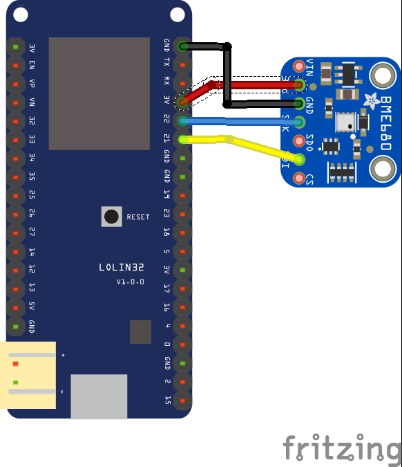
BME680
Temp, Humidity, Pressure & gas
BME680 is a complete environmental sensor in one. It measures temperature, humidity, pressure and VOC-gas. VOC is volatile organic carbon gasses. It's burned organic compounds, or organic solvents that easily evaporate due to low boiling point, as ethanol and other alcohols. The The VOC-gas sensor does not measure a specific gas, but gives some information about the total concentration of VOC gasses, normally informing you about the "quality of the climate" for humans to be in.
Connect
Code & Setup
short version of the Adafruit guide
- Install libraries:
Menu: Sketch / Include Library / Manage Library. and search for: - "Adafruit BME680 Library"
- "adafruit unified sensor"
- Restart Arduino IDE
- Use the code below or load the example
Menu: File / Example / adafrui680 / bme680test. - Open the serial monitor to see the data
/*
  Written by Limor Fried & Kevin Townsend for Adafruit Industries.
  BSD license, all text above must be included in any redistribution
 */

#include <Wire.h>
#include <SPI.h>
#include <Adafruit_Sensor.h>
#include "Adafruit_BME680.h"

#define BME_SCK 13
#define BME_MISO 12
#define BME_MOSI 11
#define BME_CS 10

#define SEALEVELPRESSURE_HPA (1033.4)

Adafruit_BME680 bme; // I2C
//Adafruit_BME680 bme(BME_CS); // hardware SPI
//Adafruit_BME680 bme(BME_CS, BME_MOSI, BME_MISO,  BME_SCK);

void setup() {
  Serial.begin(9600);
  while (!Serial);
  Serial.println(F("BME680 test"));

  if (!bme.begin()) {
    Serial.println("Could not find a valid BME680 sensor, check wiring!");
    while (1);
  }

  // Set up oversampling and filter initialization
  bme.setTemperatureOversampling(BME680_OS_8X);
  bme.setHumidityOversampling(BME680_OS_2X);
  bme.setPressureOversampling(BME680_OS_4X);
  bme.setIIRFilterSize(BME680_FILTER_SIZE_3);
  bme.setGasHeater(320, 150); // 320*C for 150 ms
}

void loop() {
  if (! bme.performReading()) {
    Serial.println("Failed to perform reading :(");
    return;
  }
  Serial.print("Temperature = ");
  Serial.print(bme.temperature);
  Serial.println(" *C");

  Serial.print("Pressure = ");
  Serial.print(bme.pressure / 100.0);
  Serial.println(" hPa");

  Serial.print("Humidity = ");
  Serial.print(bme.humidity);
  Serial.println(" %");

  Serial.print("Gas = ");
  Serial.print(bme.gas_resistance / 1000.0);
  Serial.println(" KOhms");

  Serial.print("Approx. Altitude = ");
  Serial.print(bme.readAltitude(SEALEVELPRESSURE_HPA));
  Serial.println(" m");

  Serial.println();
  delay(2000);
}
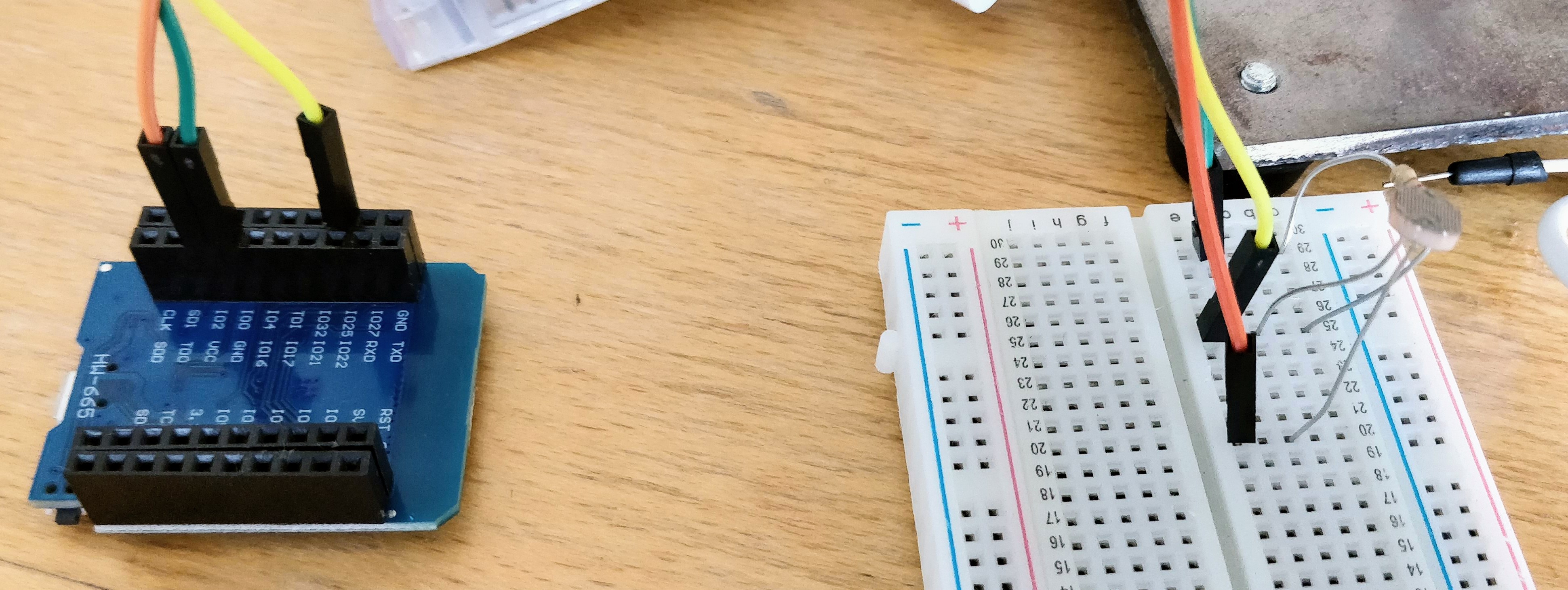
Photoresistor
A photoresistor is a light-controlled variable resistor. It can be used to measure light intensity. You need to connect it to one of the analog pins of your microcontroller and use a pulldown resistor. The pull down resistor prevents unknown states.
The ESP32 has two analog pins, these are IO25 and IO26 that read values that range from 0 to 4095.
Wiring
WEMOS ESP 32 Wiring
ARDUINO UNO Wiring
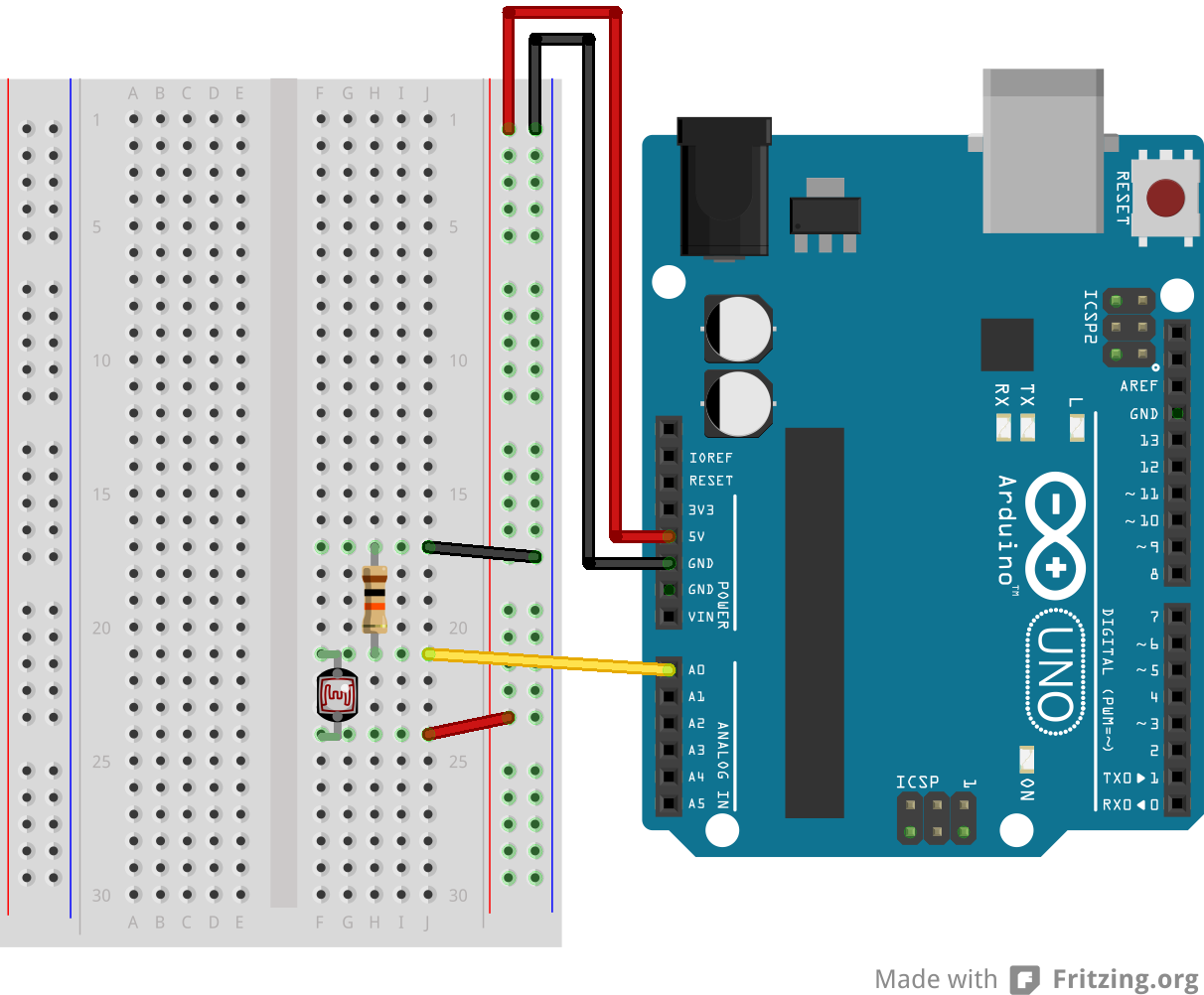
/* Simple test of the functionality of the photoresistor
Connect the photoresistor one leg to pin IO25, and pin to +5V
Connect a resistor (around 10k is a good value, higher
values gives higher readings) from pin 0 to GND.*/

int lightPin = 25;  //define a pin for Photoresistor


void setup()
{
    Serial.begin(9600);  //Begin serial communication
}

void loop()
{
    Serial.println(analogRead(lightPin)); //Write the value of the photoresistor to the serial monitor.

   delay(10); //short delay for faster response to light.
}
Neopixel
Instal the Fastled library.
Go to sketch->include library -> manage libraries->search for Fastled and install it.
You might need to restart the arduino
Wiring
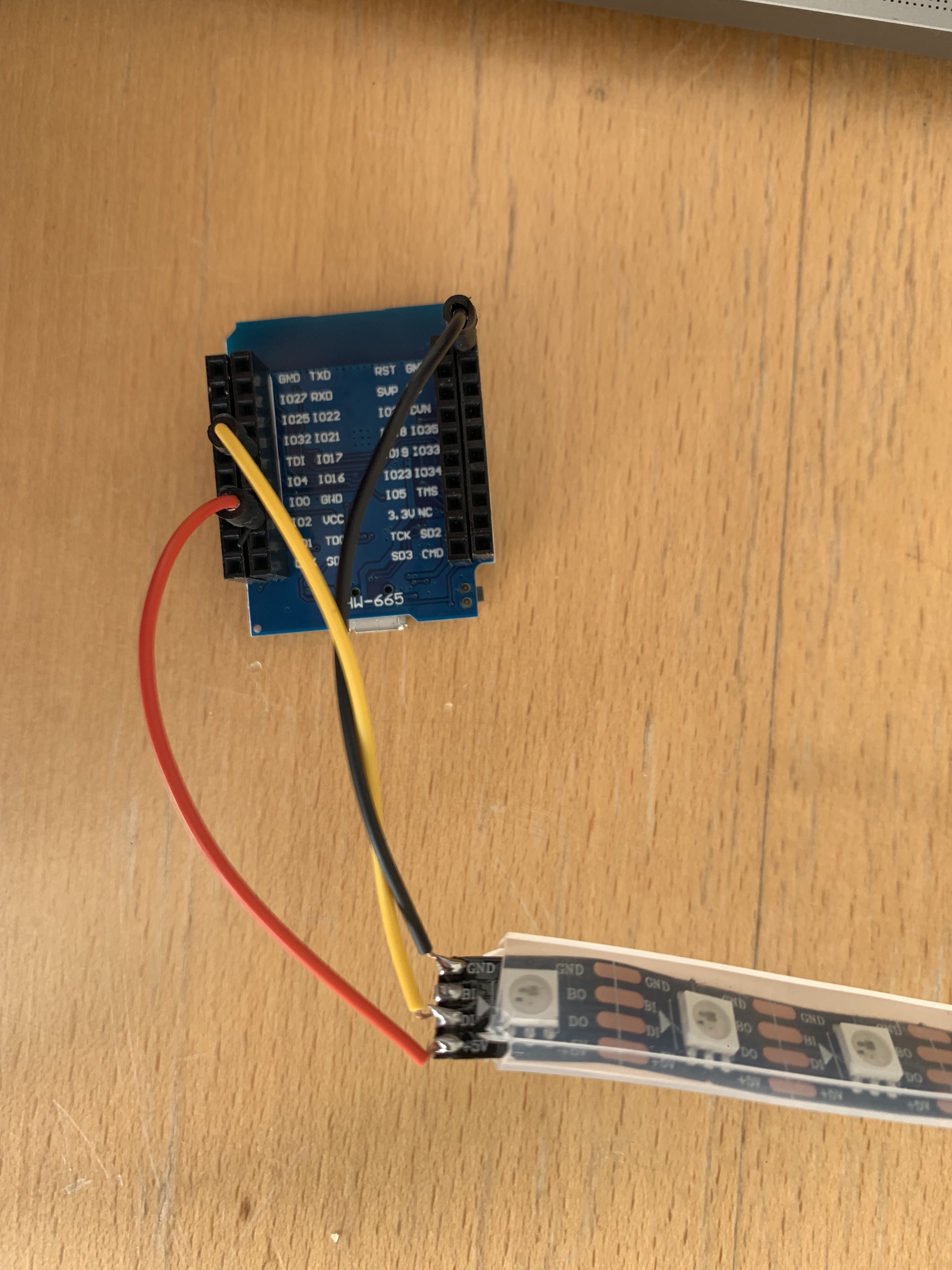 5V - VCC
GND - GND
DI - IO17
IMPORTANT: connect 5v to 5v on the arduino, DI to Digital Pin 4 and GND to GND. Make sure this is correct:
![]()
Code
The examples below are just a few of the things you can do. See this collection for more inspiration.
This example sketch will turn red, green and blue for the first three pixels:
  #include "FastLED.h"

  // How many leds in your strip?
  #define NUM_LEDS 10
  #define DATA_PIN 17


  // Define the array of leds
  CRGB leds[NUM_LEDS];

  void setup() {
          FastLED.addLeds<NEOPIXEL, DATA_PIN>(leds, NUM_LEDS);
  }

  void loop() {
    // Turn the LED 1,2,3 on
    leds[0]= CRGB( 255, 0, 0);
    leds[1]= CRGB( 0, 255, 0);
    leds[2]= CRGB( 0, 0, 255);
    FastLED.show();

  }
This example will turn all the 12 leds red:
#include "FastLED.h"

// How many leds in your strip?
#define NUM_LEDS 13
#define DATA_PIN 4


// Define the array of leds
CRGB leds[NUM_LEDS];

void setup() {
  FastLED.addLeds<NEOPIXEL, DATA_PIN>(leds, NUM_LEDS);
}

void loop() {

  for (int i = 0; i < NUM_LEDS; i = i + 1)
  {
    leds[i] = CRGB( 255, 0, 0);
  }
  FastLED.show();

}
This example makes a chase
#include "FastLED.h"

// How many leds in your strip?
#define NUM_LEDS 13
#define DATA_PIN 17


// Define the array of leds
CRGB leds[NUM_LEDS];

void setup() {
  FastLED.addLeds<NEOPIXEL, DATA_PIN>(leds, NUM_LEDS);
  Serial.begin(9600);
}
int numLedsOn = 0;
void loop() {

  for (int i = 0; i < NUM_LEDS; i = i + 1)
  {
    if (i < numLedsOn)
    {
      leds[i] = CRGB( 255, 0, 0);
    }
    else
    {
      leds[i] = CRGB( 0, 0, 0);
    }
  }

  FastLED.show();
  numLedsOn = numLedsOn + 1;
  if (numLedsOn == NUM_LEDS)
  {
    numLedsOn = 0;
  }
  Serial.println(numLedsOn);

  delay(100);

}
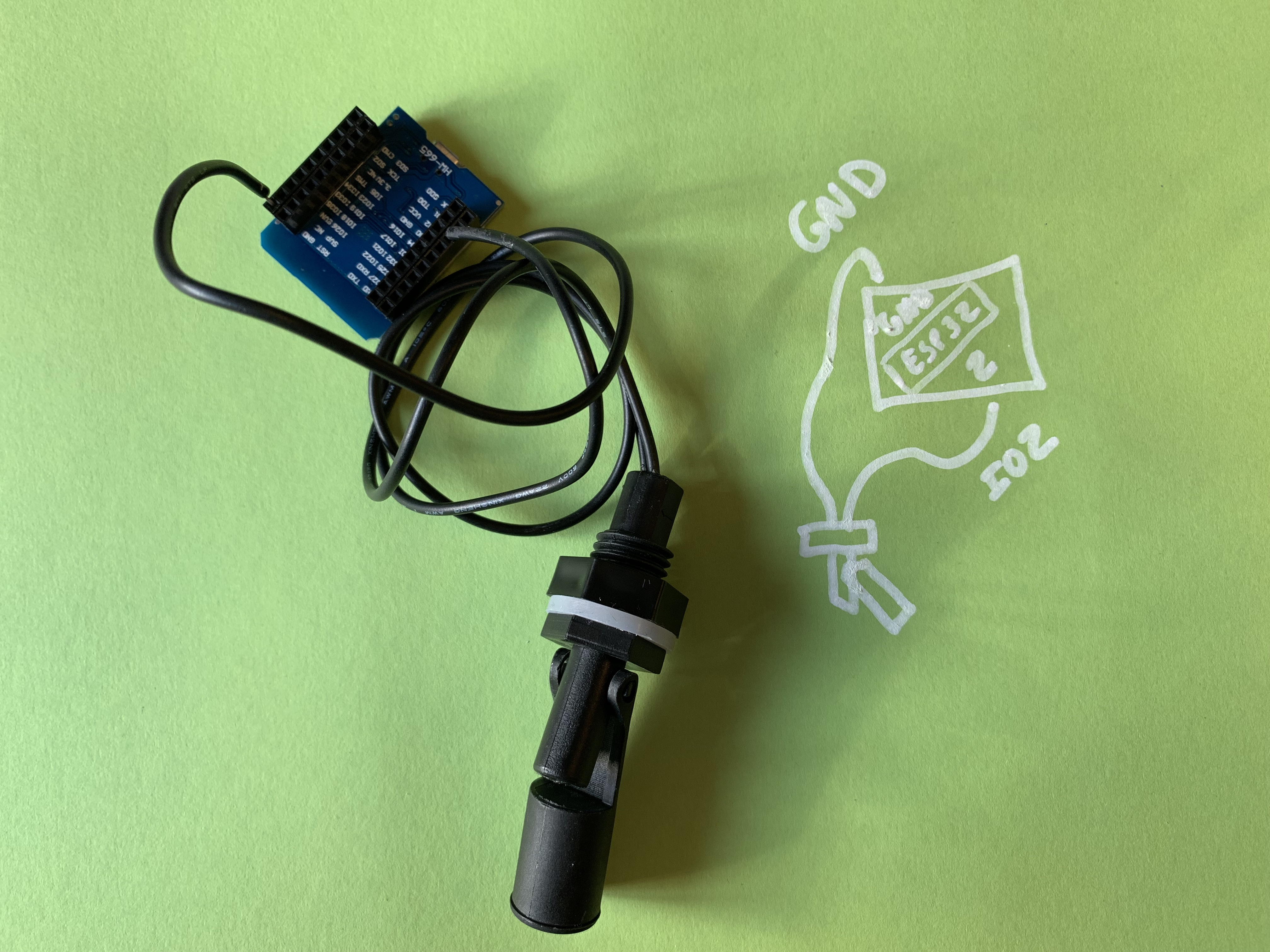
Water Level
This water level sensor works as a switch. It can be open or closed.
void setup()
{
  pinMode(2, INPUT_PULLUP);
  Serial.begin(9600);

}

void loop()
{
  boolean waterLevel = !digitalRead(2);

  if (waterLevel == true) {
    Serial.println("Water level high");

  } else {

    Serial.println("Water level low");

  }

}
  }

}
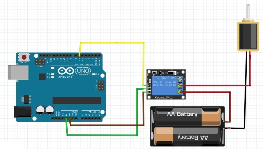
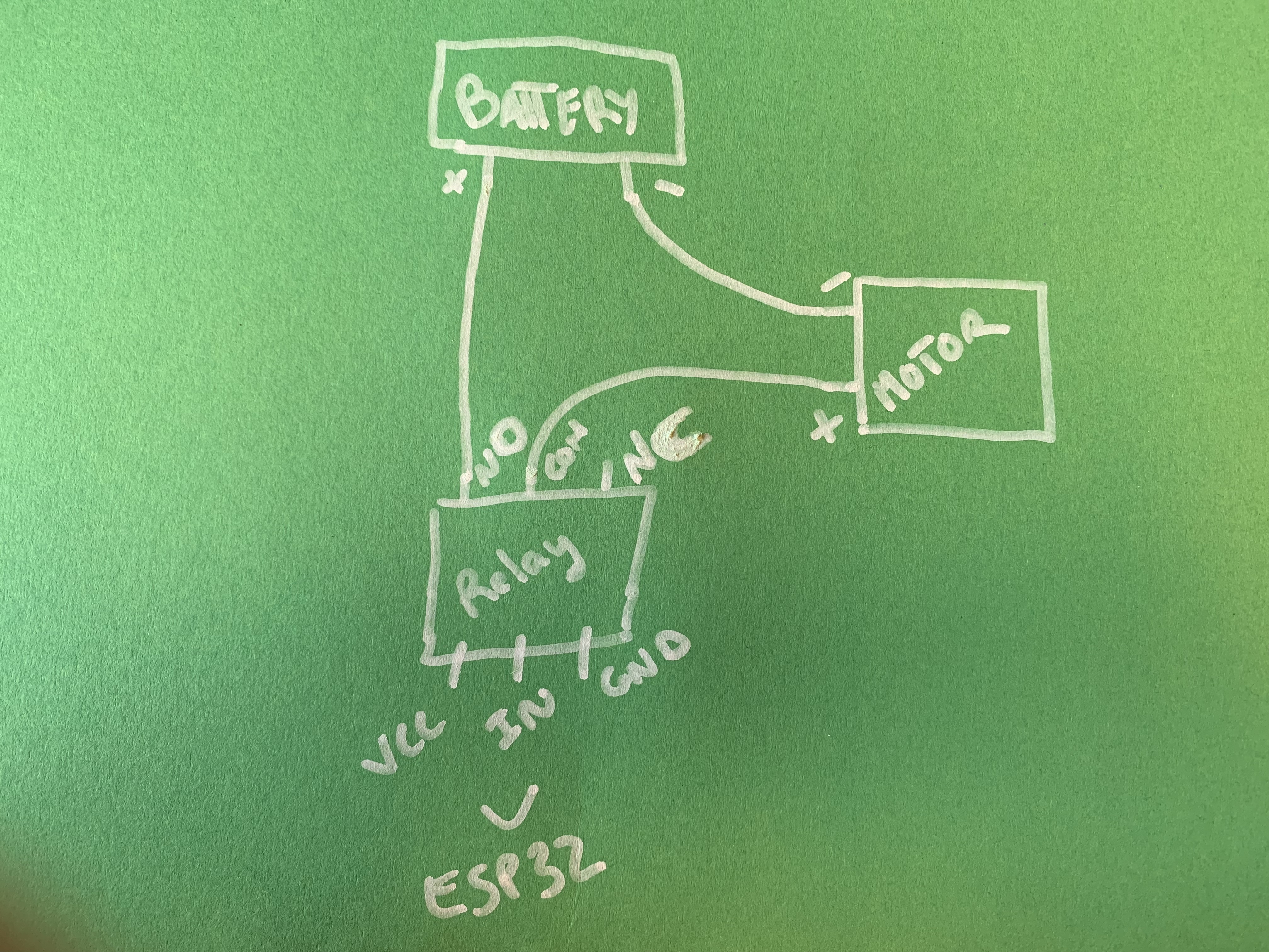
Relay & Motor control
To control a high voltage motor with an Arduino you can use a relay.
Since the Arduino operates at 5V it can't control higher voltage devices directly. You can use a 5V relay to switch the 120-240V motor on and off.
Have in mind that you can't use the same power source to power a 12v motor and a ESP32. You need a 12V to 5V converter to power up your microcontroller if you want to use the same battery to power up the entire system.
#define motor 5

void setup()
{
  pinMode(motor,OUTPUT);
}

void loop()
{
  digitalWrite(motor,HIGH);
  delay(5000);
  digitalWrite(motor,LOW);
  delay(5000);
}
Touch Sensing
The board has a build in touch sensor function (capacity touch).
It works on the pins: 0,2,4,12,13,14,15,27. You connect a wire to the pin, and then to a piece of metal or aluminium foil to make the touch pad. ESP32 touch guide
Simple read code
// ESP32 Touch Test
// Just test touch pin - Touch0 is T0 which is on GPIO 4.

void setup() {
  Serial.begin(115200);
  delay(1000); // give me time to bring up serial monitor
  Serial.println("ESP32 Touch Test");
}

void loop() {
  Serial.println(touchRead(4));  // get value of Touch 0 pin = GPIO 4
  delay(200);
}
Code that make the on board LED blink
#define TOUCH_PIN 4 //connected to 4
#define LED_PIN 2 //connected to 15
int touch_value = 100;

void setup()
{
Serial.begin(115200);
Serial.println("ESP32 Touch ");
pinMode(LED_PIN, OUTPUT);
digitalWrite (LED_PIN, LOW);
}

void loop()
{
touch_value = touchRead(TOUCH_PIN);
Serial.println(touch_value); // get value using T0
if (touch_value < 30)
{
digitalWrite (LED_PIN, HIGH);
}
else
{
digitalWrite (LED_PIN, LOW);
}
delay(100);
}
Magnetic sensing (Hall Sensor)
The board also have a magnetic sensor build into the chip. You don't need to do any wiring, just set the magnet close to the chip on the board. The values approximately goes from -150 to + 50.
magnetic sensor exmple
// Simple sketch to access the internal hall effect detector on the esp32.
// values can be quite low.
// Brian Degger / @sctv

int val = 0;

void setup() {
  Serial.begin(115200);
}

// put your main code here, to run repeatedly
void loop() {
  // read hall effect sensor value
  val = hallRead();
  // print the results to the serial monitor
  Serial.println(val);
  delay(150);
}