Laser cut a topographic map
This is a two part guide, one that explains the workflow on QGIS and one that goes through the process on Adobe Illustrator to make the files ready for the laser cutter.
On QGIS (3.8)
- DATA
From Denmark download data here:
https://dataforsyningen.dk/data
Danmakrs Højdemodel - Terræn - DHM /DEM Terrain data
GeoDenmark data set has bygninger, bebyggelse, trafik, teknik, natur, hydro og administrative inddelinger.
QGIS
Download and open QGIS (go for version 3.8) (Open source GIS software)LOAD RASTER LAYERS
Open your data on QGIS. Drag and drop it on the layers window or Layer -> Data Source manager -> Raster -> Find your data -> press AddMERGE RASTER
If you have more then one raster tile you need to merge them. Go to Raster menu -> Miscellaneous -> Merge. Choose the input layers you want to merge and press run . (I could not get this function to work on version 3.10 - I had to install the 3.8 version and work on this one)CONTOUR
Now you need to make the contour.
Go to menu Raster -> Extraction -> Contour. Set the parameters that suit your project. I've only changed Interval between contour lines to 2,5 meters because the geographical area I'm working with only has a 15 meters altitude, meaning I will end up having 6 layers.SIMPLIFY
You can now see that the contour has a lot of details. This can be difficult to cut. Use the tool simplify to reduce the amount of detail. Go to menu Vector -> Geometry Tools -> Simplify
Choose the contours as the input layer. I will go with a tolerance of 20 meters, but you might want to try different sizes to get a simplified line that suits your project.SMOOTH
Because the simplify tool makes very sharp curves you might want to smoothen them.
Another way of accessing the processing tools is by searching for a tool in the processing toolbox. If it isn't open already you can find it by going to menu processing and clicking on Tools. A new tool window will appear.
Search for Smooth and click on it. Change the setting until they feet your design. I achieve the best result by changing iteration to 5.Delete small shapes
There will probably be many small shapes that will be difficult to cut and disturbing the understanding of your model. To delete these you need to make a new field containing the length and then filter the small ones out.
Right-click on the layer -> Open table attributes -> open Field calculator. Make a new field; name it Lenght and from the left list open Geometry and press $lenght as Expression. Press OK. This will create a new field containing the length of every attribute. make sure you turn Edit mode off (press on the pen). Close the window.
Now, right-click on the layer and choose Filter. Here you choose the new field. I have chosen the following expression "Lenght" > 50. Meaning I only want my layer to show me the fields that have a length above 50. You choose a condition that makes sense for your project.Classify by elevation
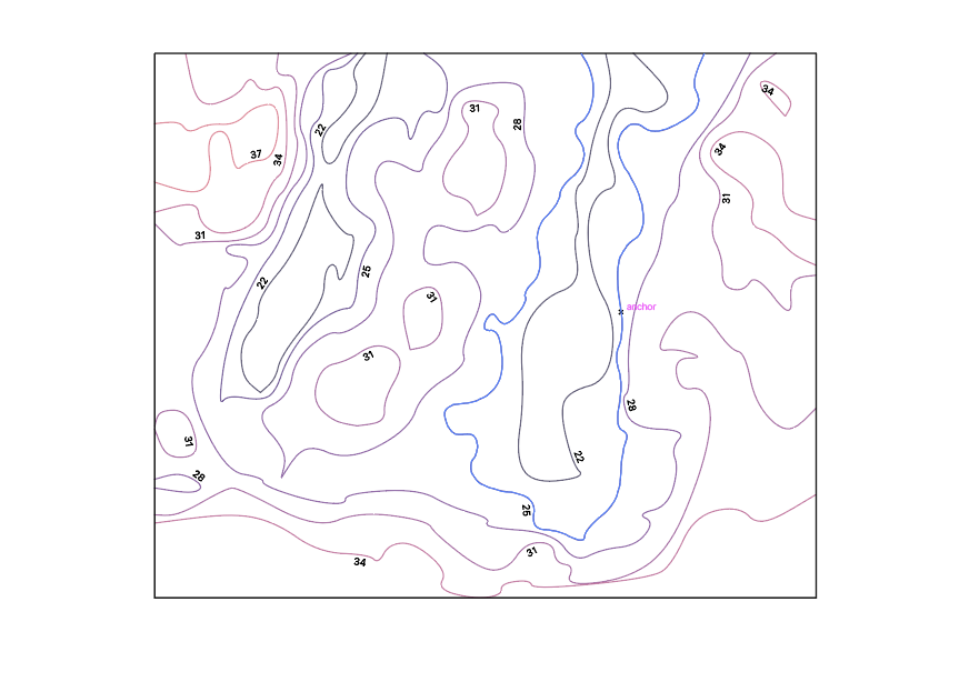
To be able to differentiate the different elevation layers we classify them by colors. This makes it possible, later on, to make the different files for cutting.
Right-click, choose Properties, press Symbology and choose Categorized, choose Elev layer as Column, and choose what color ramp that makes sense to you.Export vector file
We now have a file that can be exported to a vector-drawing program.
Right-click, choose Export -> Save Feature as -> save it as a DXF.
OR
If you want the diferent elevations to be exported as diferent layers to work with it in illustrator, you can duplicate the layer, only have on elevation visible for every shape file. So you have one elevation per shapefile. You can know export dxf by going to Project -> Export -> Export project to DXF -> choose all the layers you want, give it a name and choose a place to save it. Your DXF will now have different elevations on each layer.
On Adobe Illustrator
I'm using Adobe Illustrator to make the files ready for the laser cutter. You can use other vector drawing programs to do the same. The main thing here is the workflow.
If you open your DXF file in Illustrator it will look like this:
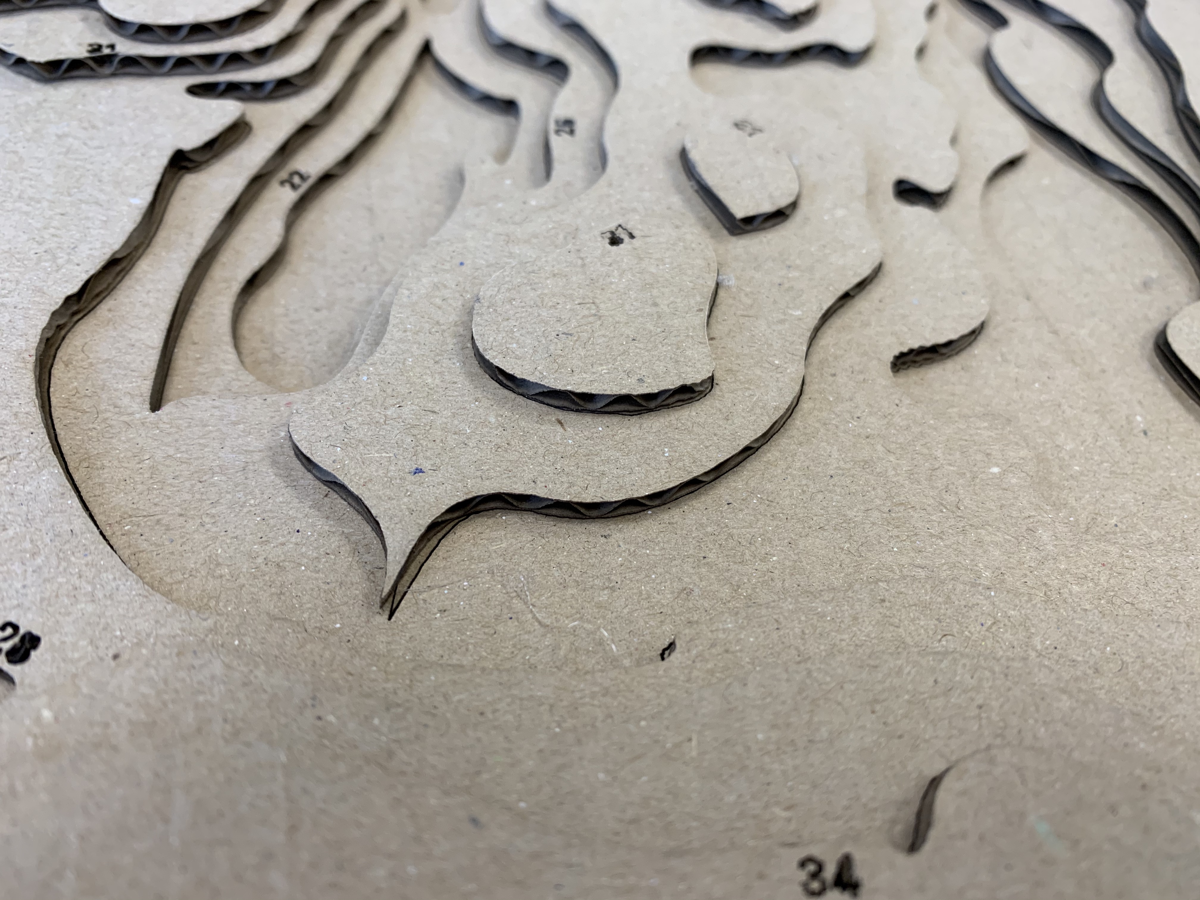
You need to cut every elevation layer by it self to be able to build the map in height.
To know where to place the next layer you need to engrave it into the previous layer. To be able to have the laser cutter to perform two different task (cut - black line & engrave - red line) the lines need to have different colors.
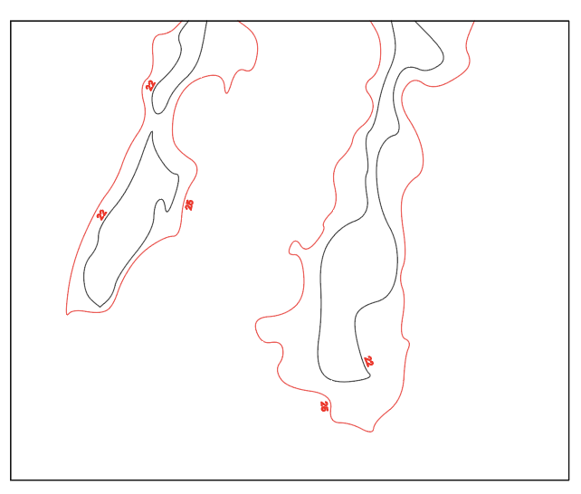
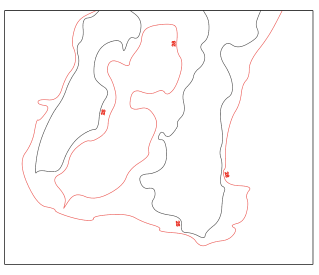
Make a file for every layer, where you have the line(s) for the layer in question and the next. You start from the lowest elevation layer (use the number /color to find them). Then give them new colors (red and black) See pictures:
 Layer 0 (lowest layer)
 Layer 1
 Layer 2
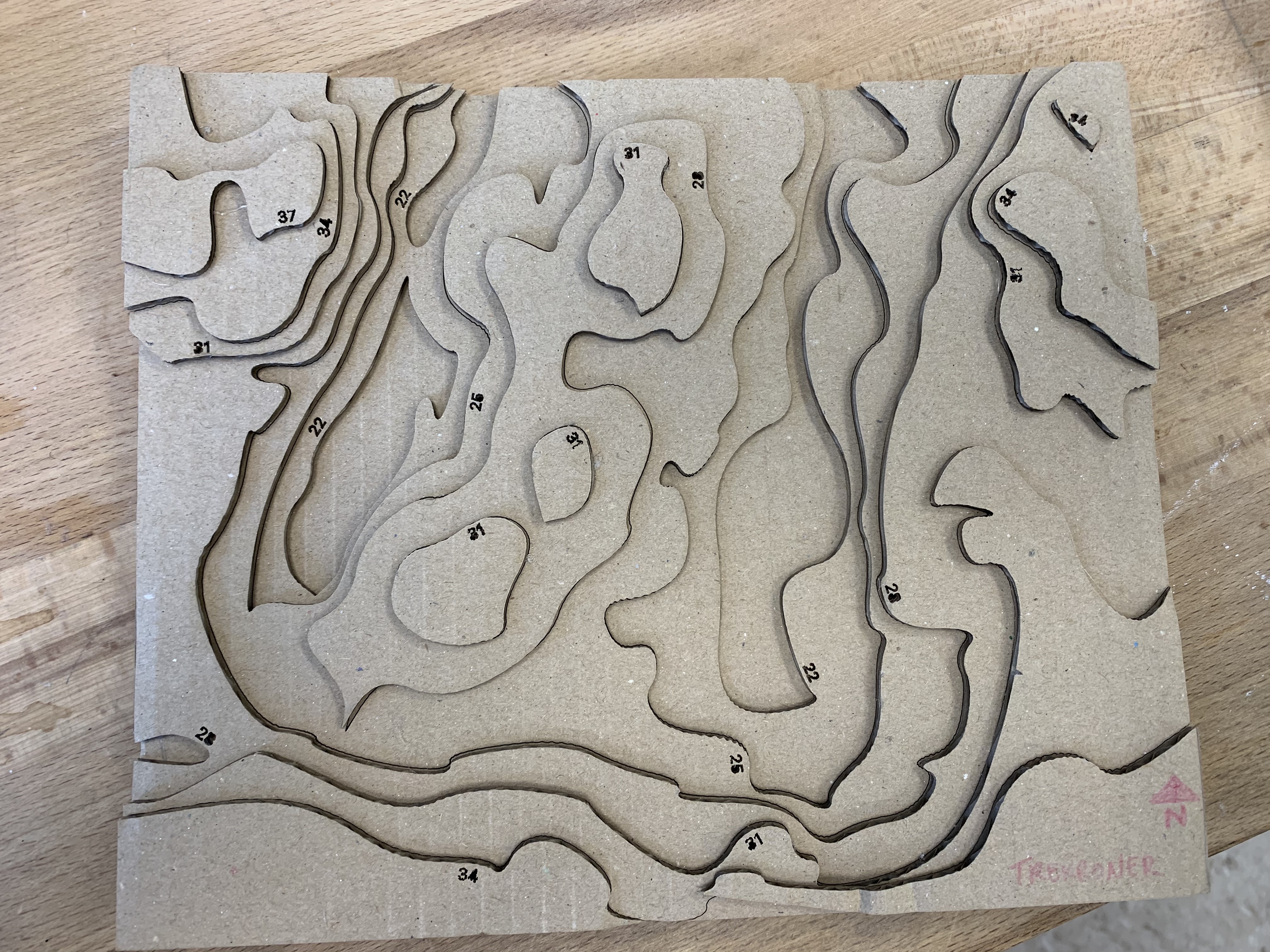
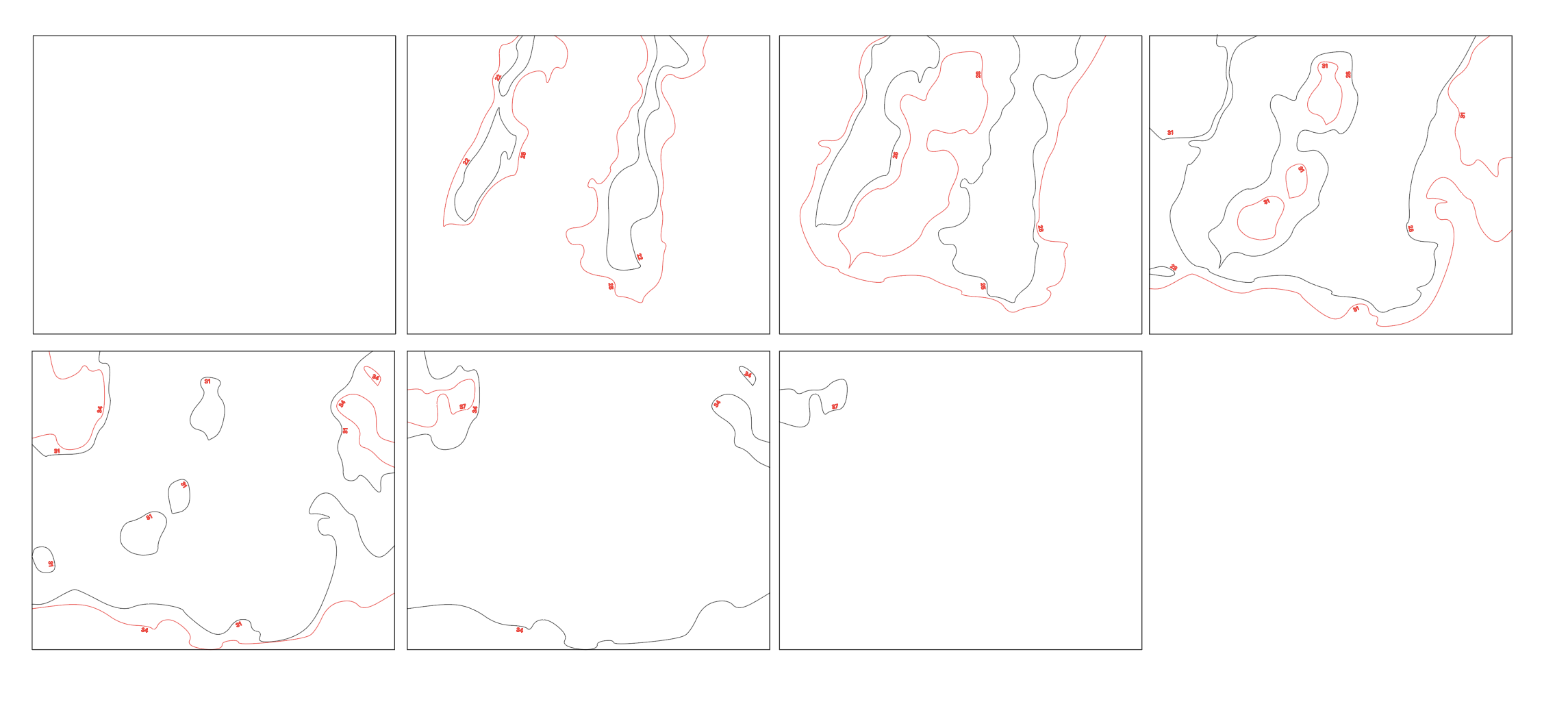
Here all the files ready for lasercutting:
 When you have all the files ready you are ready to get them lasercutted. See how here: https://fablab.ruc.dk/lasercutter-guide/