RFID from Arduino to Processing
RFID is a chip with a unique code that can be used in many ways. This guide will show one way to use the RFID chip as input in a Processing program. To follow this tutorial you need:
- Any number of RFID chips
- RFID-reader
- Arduino UNO with USB-cable
- A computer with Processing and Arduino IDE
When you're done you can change the color of a square in processing to different colors with different RFID-chips placed on a RFID-reader.
Arduino
The Arduino is used for translating the RFID-chip signals from the RFID-reader into a String and send a Serial message to the computer.
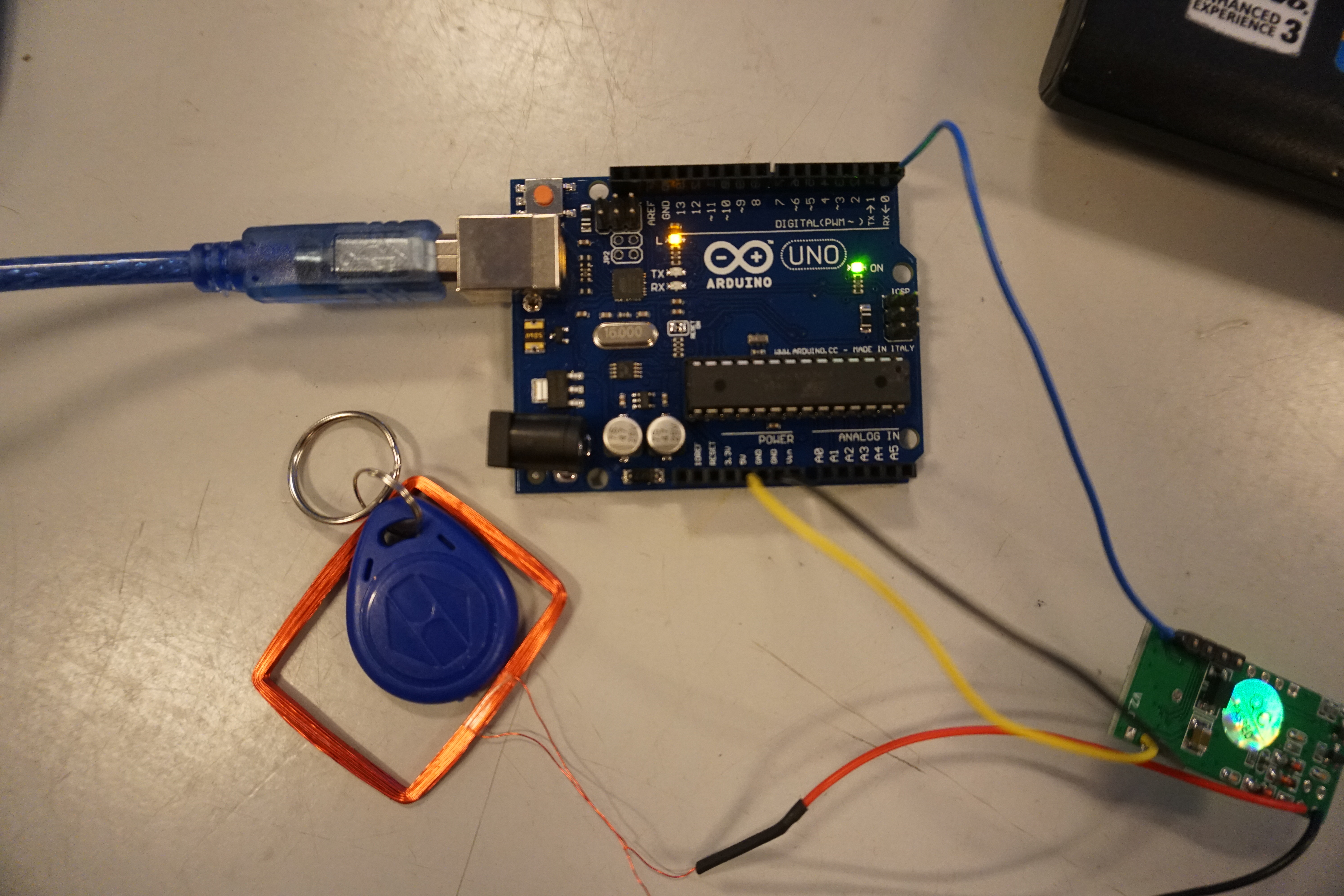
We will start connecting the RFID-reader with the Arduino and then program it with the Arduino IDE.
RFID-reader to Arduino
We use the RDM6300 RFID-reader in this guide.
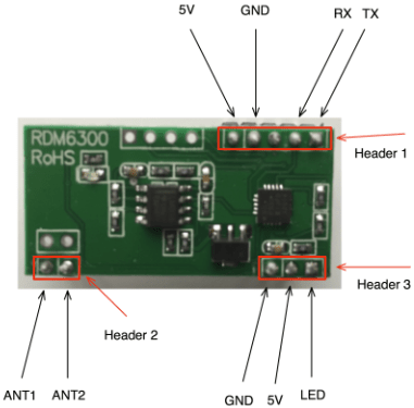
The RFID-reader needs 5v and ground (GND) to get power and then we use the TX pin to send signals to the Arduino. The Arduino recieves the signal through the RX pin (Digital PIN 0).
When the RFID-chip is placed on the reader it sends some electronic signals to the Arduino that represents characters in a special order. We need some code to read this string of characters in a proper way. If we don't the Arduino can still read the characters but it will be kind of random how many of the characters that we will send to the computer. Therefore you should upload this code to your Arduino (read the comments in the code if you want to understand the steps).
WARNING: The code won't upload if the RX/TX wire is connected
#define TIMEOUT 200

//reader class that makes a String from the RFID-chip input
class reader
{
  public:
    unsigned long timer;
    String input;
    int state;

    //Sets the state of the switch to 0
    reader()
    {
      state = 0;
    }

/*Method that gets chars and adds them to the input string. The char string actually looks something like ("2-27-5-39-47-39-3")
The start of the text will be represented by the number 2 and the end by 3. Thats the Ascii way of telling the start of text and the end of text. We are only interested in sending the information inbetween those two numbers. This method will help sorting this out in the right way.*/

  bool data(char c)
    {
      bool result = false;

      switch (state)
      {

/*Because the RFIDs first char is always 2, the program can clean the input string. The program then sets the state to 1.*/

        case 0:
          if (c == 2)
          {
            input = "";
            state = 1;
          }
          break;

/*The RFIDs last character is always 3. Therefore the program can add chars to the input string until it reach the character 3.
When the program reach the char 3, the result is true and the programs tracks the time. That's because we need a timeout where the program can't add more chars to the string.*/

        case 1:
          if (c == 3)
          {
            timer = millis();
            result = true;
            state = 2;
          }
          else
          {
            input += c;
          }
          break;

        case 2:
          timer = millis();
          break;
      }
      return result;
    }

/*This methods is updating the state to 0 when the timeout is reached*/

    void update()
    {
      if (state == 2)
      {
        if (millis() > timer + TIMEOUT)
          state = 0;
      }
    }
};

//Initialize a reader named port1
reader port1;

void setup()
{

  //Begins the serial communication with a baudrate

  Serial.begin(9600);

}


void loop()

{

/*This is running when the serial is available and if there is a data input it will print the input string*/

  while
  (Serial.available())
  {
    if (port1.data(Serial.read()) == true)
    {
      Serial.println(port1.input);
    }
  }
  port1.update();
}
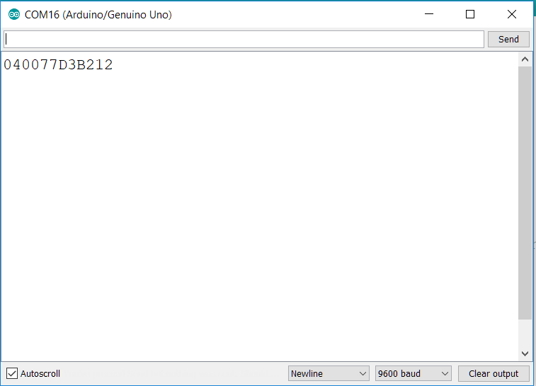
You can test if the code and wiring is working by putting a RFID-chip on the reader while have the Serial monitor open in Arduino. If everything is connected in the right way you will get a message like this everytime you put a RFID chip on the reader.
When you're done testing close the monitor. The port that recieves the serial messages can't send information to the Serial Monitor and Processing at the same time.
Processing
Library and variable declarations
Now you're ready to recieve the data with Processing. We start with declaring some variables that refers to our serial port, dataread and state. The import statement includes the serial library and gives processing the functions needed to recieve data through the serial port.
import processing.serial.*;

Serial myPort;         // The serial port
String finalRead = ""; // Variable with final data
String inputRead = ""; // Variable that recieves the data
int state = 0;         // Variable to store the program state
Setup
Now we need to setup the program. This code is only runned once. The code setup the program window and initialize the serial port.
void setup() {

  size(800, 800); //Size of the program window
  background(50, 50, 150); //Background colour

  // List all the available serial ports
  printArray(Serial.list());

  // Open the port you are using at the rate you want:
  myPort = new Serial(this, Serial.list()[6], 9600);

  // The rectangle will be placed based on it's own center
  rectMode(CENTER);

}
The important part is:
myPort = new Serial(this, Serial.list()[6], 9600);
The number inside the [ ] is defining which port the program listens to. When you run the program nothing will work unless you choose the right port. The program will print a list of available ports, but you need to choose the one the Arduino is attached to. You can look that up in the Arduino IDE. If the Arduino is attached to COM3 and your printed list look like this:
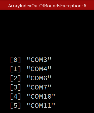
Then you need to choose change the port to:
myPort = new Serial(this, Serial.list()[0], 9600);
This tutorial is made on a windows computer and windows is known for having problems with COM ports. The ports is looking different on MAC and LINUX but the concept is the same, and they use to be more stable on UNIX based operating systems. When we only use one Arduino Windows is good enough, but if you you want more readers i recommend changing to a UNIX based system.
Draw
When the program setup is done the draw method can be implemented:
void draw() {

  /*When the serial port is available the data from the RFID is
    loaded into the finalRead variable.*/

  while (myPort.available() > 0)
  {
    //The c variable is updated with the read method

    char c=(char)myPort.read();

    /*
      When processing recieves data from Arduinos println command
      it is recieved with a \r in the beginning
      and a c\ in the end.
      Therefore we add c to inputRead when
      we are not encountering \r.

      If we encounter \n we know that the string is done reading.
      The string is loaded into the finalRead variable and
      the data is cleared from inputRead.
     */

    if (c=='\n')
    {
      finalRead = inputRead;
      inputRead = "";
      println("data: " + finalRead);
    } else if (c!='\r')
    {
      inputRead+=c;
    }
  }

   /*Now the program checks if the data is equal to the data
   on a wanted RFID-chip. If thats the case the state of the
   program changes. Here you need to fill in data from a specific
   RFID-chip*/

  if (finalRead.equals("0400783A7C3A")) {
    state = 1;
  }

  /*Another RFID-chip if-statement with another state. You can do this with as many RFID-chips you want.*/

  if (finalRead.equals("040047C00A89")) {
    state = 2;
  }

  /*If the state is changed to 1, the colour of the center Rectangle
    is changed to red.*/

  if (state == 1) {
    fill(200, 20, 20);
  }

  /*If the state is change to 2, the colour of the center Rectangle is changed to green.*/
  if (state == 2) {
    fill(20, 200, 20);
  }

  /*The program now draws a rectangle with a fill colour dependent on the state variable*/
  rect(width/2, height/2, width-100, height-100);
}
The code is explained in details in the code-comments. In general the first part is about reading the data and making a finalRead. The finalRead is used switching between states and the states then switches a fill color on a rectangle. The point is that the state machine could be used for other purposes like changing pictures or calling different methods.
The reading
  while (myPort.available() > 0)
  {
    char c=(char)myPort.read();

    if (c=='\n')
    {
      finalRead = inputRead;
      inputRead = "";
      println("data: " + finalRead);
    }
    else if (c!='\r')
    {
      inputRead+=c;
    }
  }
This code is the same logic as in the Arduino program. The code runs when the port is available and then reads the characters send from the Arduino. If the characters are not \r (Carriage Return) they will be added to the inputRead. If the character is \n (New Line) we are done an can load the input into a finalRead and then clean the inputRead.
The state machine
  if (finalRead.equals("0400783A7C3A")) {
    state = 1;
  }

  if (finalRead.equals("040047C00A89")) {
    state = 2;
  }

  if (state == 1) {
    fill(200, 20, 20);
  }

  if (state == 2) {
    fill(20, 200, 20);
  }

  rect(width/2, height/2, width-100, height-100);
This is a simple implementation, where if-statements sets the state, if the finalRead is equal to the data from one of your RFID chips. You neew to change the string in the if-statements to fit your own chips. Feel free to add mores states and more RFID-chips. You just need to remember that the states are executed in every frame in the runtime of the program.
You're now ready to play with the power of RFID-chips in Processing.