Environmental Kit
This introductory environmental kit allows making simple measurements and visualisations of humidity, temperature and light in a certain environment.
DHT11 & DHT22 - Temp & Humidity Sensor
Arduino
Arduino is an open-source electronics platform that is used to sense the real world, make interactive projects and prototypes.
The Arduino board is able to read inputs and write outputs. In this example, the input will be a potentiometer (a variable resistor) and the output a string of neo-pixels - individually controllable light emitting diodes. Using code, we can control how the input affects the output.
Download the Arduino software here: Arduino. This is used to program the Arduino microcontroller. Thereafter, the program is in the Arduino, and will continue to run without the computer present.
Libraries
Install the following libraries for this kit:
DHT sensor library by Adafruit,
Adafruit Unified Sensor by Adafruit,
FastLED by Daniel Garcia,
PCD8544 by Carlos Rodrigues
(Go to: "menu->sketch->include library->manage libraries")
Components
Photoresistor
A photoresistor is a light-controlled variable resistor. It can be used to measure light intensity.
Wiring
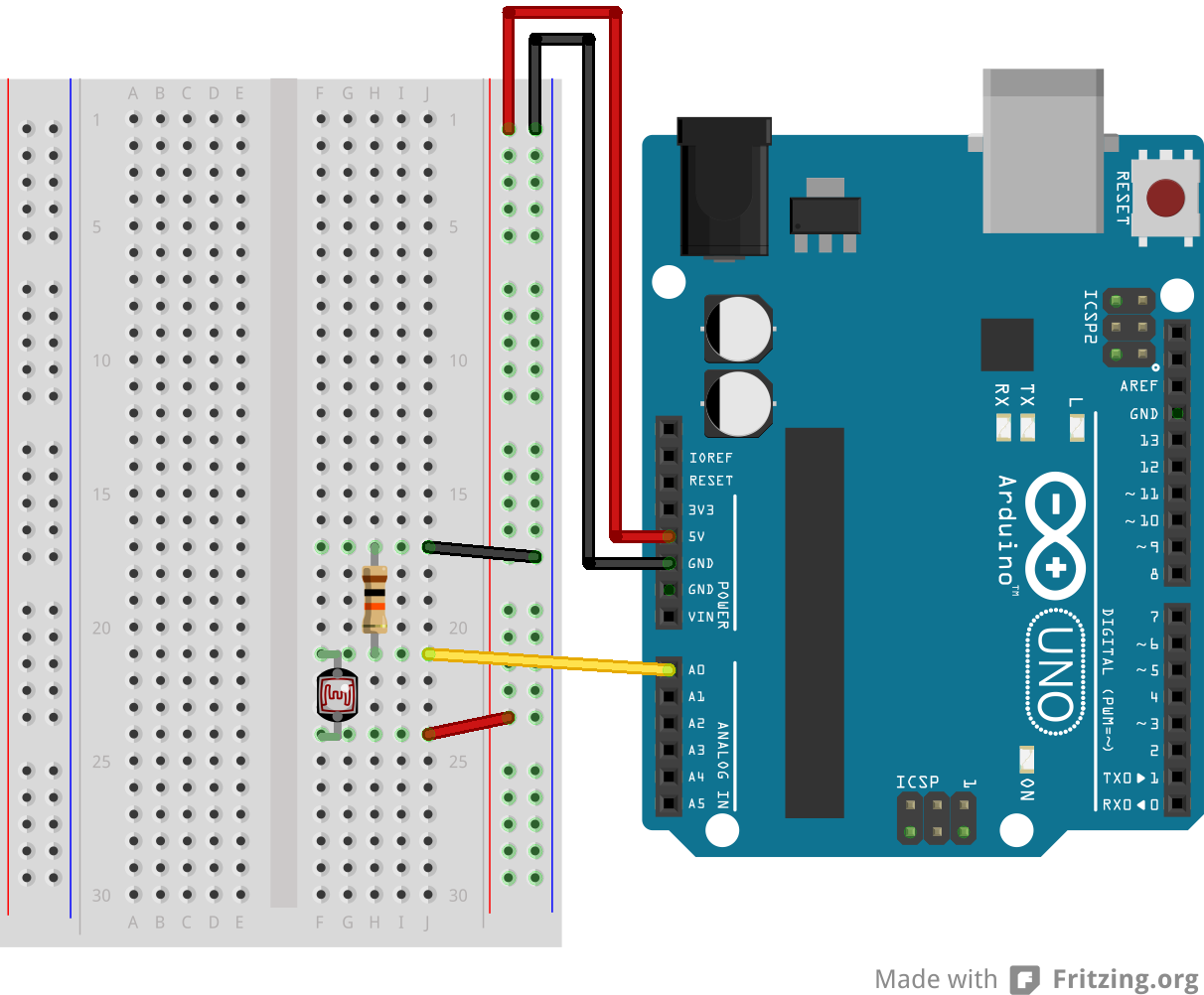
/* Simple test of the functionality of the photo resistor
Connect the photoresistor one leg to pin 0, and pin to +5V
Connect a resistor (around 10k is a good value, higher
values gives higher readings) from pin 0 to GND.*/

int lightPin = 0;  //define a pin for Photo resistor


void setup()
{
    Serial.begin(9600);  //Begin serial communcation
}

void loop()
{
    Serial.println(analogRead(lightPin)); //Write the value of the photoresistor to the serial monitor.

   delay(10); //short delay for faster response to light.
}
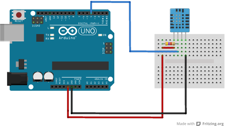
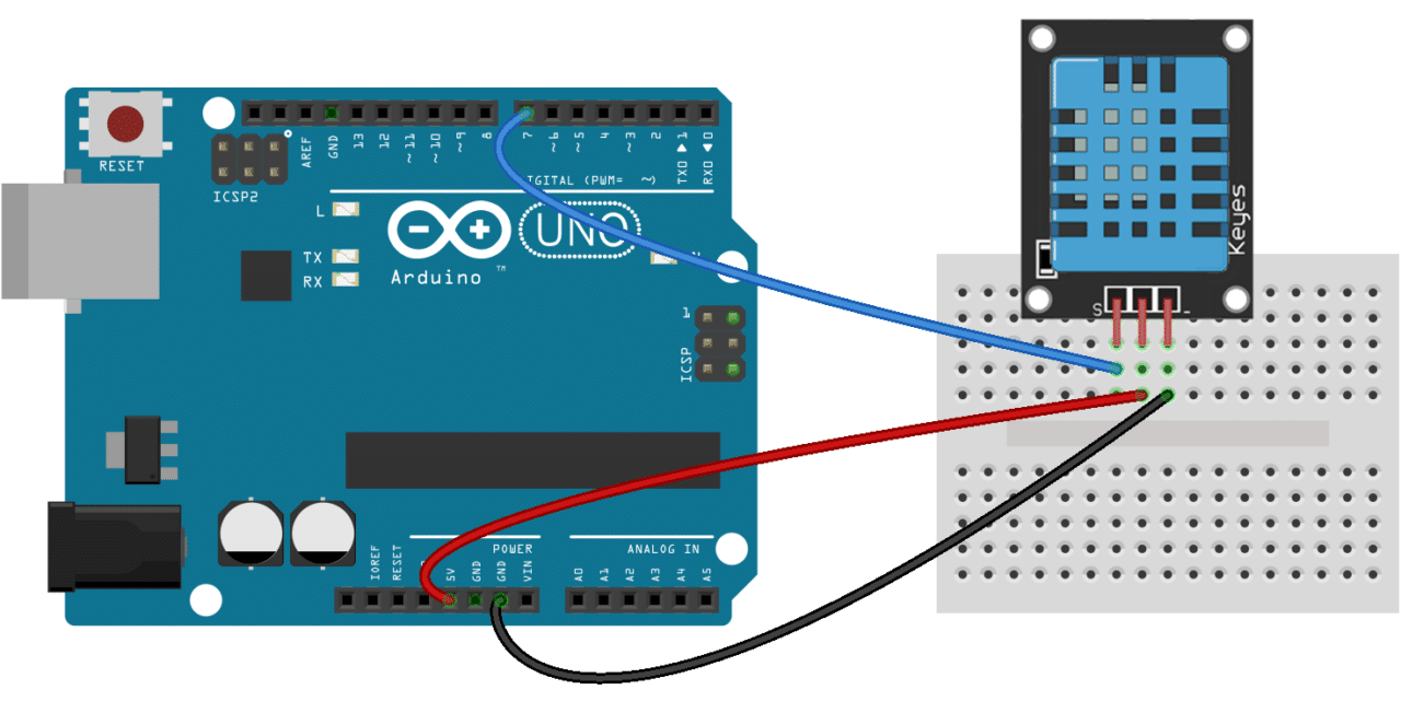
DHT11 and DHT22
DHT22(white), DHT11(blue) are low-cost temperature and humidity sensors.
Wiring
Atention: There are two types of DHT11 - one with three legs, the other with 4
4 Legs DHT11:
3 Legs DHT11:
Code
// Example testing sketch for various DHT humidity/temperature sensors
// Written by ladyada, public domain

#include "DHT.h"

#define DHTPIN 4     // what digital pin we're connected to

// Uncomment whatever type you're using!
#define DHTTYPE DHT11   // DHT 11
//#define DHTTYPE DHT22   // DHT 22  (AM2302), AM2321


DHT dht(DHTPIN, DHTTYPE);

void setup() {
  Serial.begin(9600);
  Serial.println("DHTxx test!");

  dht.begin();
}

void loop() {
  // Wait a few seconds between measurements.
  delay(2000);

  // Reading temperature or humidity takes about 250 milliseconds!
  // Sensor readings may also be up to 2 seconds 'old' (its a very slow sensor)


// Read humidity
  float h = dht.readHumidity();
  // Read temperature as Celsius (the default)
  float t = dht.readTemperature();

  // Check if any reads failed and exit early (to try again).
  if (isnan(h) || isnan(t) || isnan(f)) {
    Serial.println("Failed to read from DHT sensor!");
    return;
  }

  Serial.print("Humidity: ");
  Serial.print(h);
  Serial.print(" %\t");
  Serial.print("Temperature: ");
  Serial.print(t);
  Serial.println(" *C ");
}
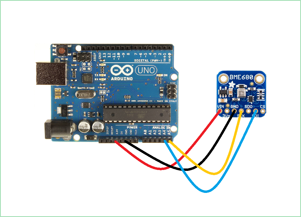
BME680
Temp, Humidity, Pressure & gas
BME680 is a complete environmental sensor in one. It meassures temperature, humidity, preassure and VOC-gas. VOC is volatile organic carbon gasses. It's burned organic compounds, or organic solvents that easily evaporate due to low boiling point, as ethanol and other alcohols. The The VOC-gas sensor does not measure a specific gas, but gives some information about the total concentration of VOC gasses, normally informing you about the "quality of the climate" for humans to be in.
Connect
Code & Setup
short version of the Adafruit guide
- Install libraries:
Menu: Sketch / Include Library / Manage Library. and search for: - "Adafruit BME680 Library"
- "adafruit unified sensor"
- Restart Arduino
- Use the code below or load the example
Menu: File / Example / adafrui680 / bme680test. - Open the serial port to see the data.
/*
  Written by Limor Fried & Kevin Townsend for Adafruit Industries.
  BSD license, all text above must be included in any redistribution
 */

#include <Wire.h>
#include <SPI.h>
#include <Adafruit_Sensor.h>
#include "Adafruit_BME680.h"

#define BME_SCK 13
#define BME_MISO 12
#define BME_MOSI 11
#define BME_CS 10

#define SEALEVELPRESSURE_HPA (1033.4)

Adafruit_BME680 bme; // I2C
//Adafruit_BME680 bme(BME_CS); // hardware SPI
//Adafruit_BME680 bme(BME_CS, BME_MOSI, BME_MISO,  BME_SCK);

void setup() {
  Serial.begin(9600);
  while (!Serial);
  Serial.println(F("BME680 test"));

  if (!bme.begin()) {
    Serial.println("Could not find a valid BME680 sensor, check wiring!");
    while (1);
  }

  // Set up oversampling and filter initialization
  bme.setTemperatureOversampling(BME680_OS_8X);
  bme.setHumidityOversampling(BME680_OS_2X);
  bme.setPressureOversampling(BME680_OS_4X);
  bme.setIIRFilterSize(BME680_FILTER_SIZE_3);
  bme.setGasHeater(320, 150); // 320*C for 150 ms
}

void loop() {
  if (! bme.performReading()) {
    Serial.println("Failed to perform reading :(");
    return;
  }
  Serial.print("Temperature = ");
  Serial.print(bme.temperature);
  Serial.println(" *C");

  Serial.print("Pressure = ");
  Serial.print(bme.pressure / 100.0);
  Serial.println(" hPa");

  Serial.print("Humidity = ");
  Serial.print(bme.humidity);
  Serial.println(" %");

  Serial.print("Gas = ");
  Serial.print(bme.gas_resistance / 1000.0);
  Serial.println(" KOhms");

  Serial.print("Approx. Altitude = ");
  Serial.print(bme.readAltitude(SEALEVELPRESSURE_HPA));
  Serial.println(" m");

  Serial.println();
  delay(2000);
}
SDS011
Laser Dust Sensor
Wiring
SDS011 - WEMOS ESP8266
RXD - D7
TXD - D6
5V - 5V
GND - GND
Library: Download here
Code
// SDS011 dust sensor example for WEMOS ESP8266
// -----------------------------
//
// By R. Zschiegner (rz@madavi.de).
// April 2016

#ifdef ESP32
#error ESP32 does not work with SoftSerial, use HardwareSerial example instead
#endif


#include <SDS011.h>

float p10, p25;
int error;

SDS011 my_sds;

void setup() {
  my_sds.begin(D6, D7); //RX, TX
  Serial.begin(9600);
}

void loop() {
  error = my_sds.read(&p25, &p10);
  if (!error) {
    Serial.println("P2.5: " + String(p25));
    Serial.println("P10:  " + String(p10));
  }
  delay(100);
}
Button
Wiring
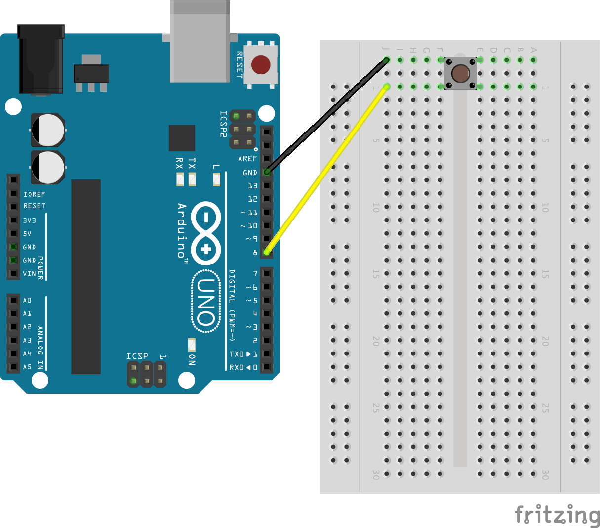
Code
void setup() {
    pinMode(8, INPUT_PULLUP);
    Serial.begin(9600);

}

void loop() {
    if (digitalRead(8) == LOW) {
      Serial.println("Button one is pressed!");
 }
    delay(100);
}
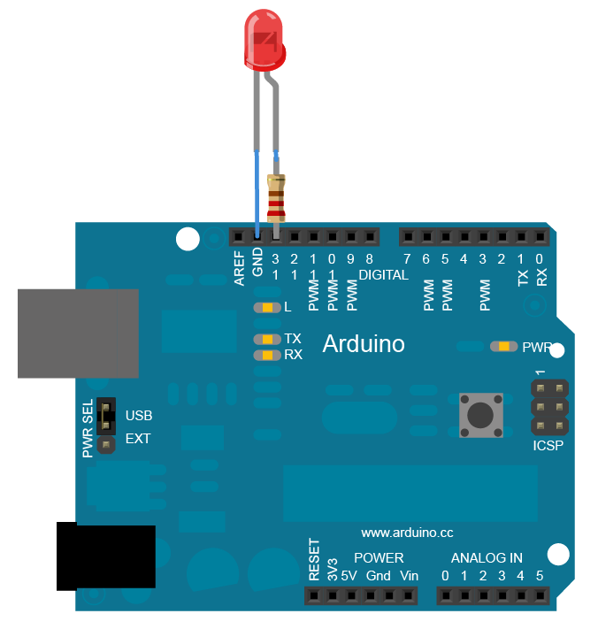
LED Blink
See a long description on the arduino website
Connect
The long leg is + (positive) the flat side is - (negative).
The resister is approximately 220 Ohm.
Code
/*
  Blink, arduino. This example code is in the public domain.  http://www.arduino.cc/en/Tutorial/Blink
*/


// Assign a pin number to a LED function
int LED1 = 13;
//int LEDCO2 = 7;

// the setup function runs once when you press reset or power the board
void setup() {
  // initialize digital pin LED_BUILTIN as an output.
  pinMode(LED1, OUTPUT);
  //pinMode(LEDCO2, OUTPUT);
}

// the loop function runs over and over again forever
void loop() {
  digitalWrite(LED1, HIGH);   // turn the LED on (HIGH is the voltage level)
  //digitalWrite(LEDCO2, HIGH);
  delay(1000);                       // wait for a second
  digitalWrite(LED1, LOW);    // turn the LED off by making the voltage LOW
  //digitalWrite(LEDCO2, LOW);
  delay(1000);                       // wait for a second
}
Neopixel
![]()
IMPORTANT: connect 5v to 5v on the arduino, DI to Digital Pin 2 and GND to GND. Make sure this is correct:
![]()
This example sketch will turn red, green and blue for the first three pixels:
  #include "FastLED.h"

  // How many leds in your strip?
  #define NUM_LEDS 10
  #define DATA_PIN 4


  // Define the array of leds
  CRGB leds[NUM_LEDS];

  void setup() {
          FastLED.addLeds<NEOPIXEL, DATA_PIN>(leds, NUM_LEDS);
  }

  void loop() {
    // Turn the LED 1,2,3 on
    leds[0]= CRGB( 255, 0, 0);
    leds[1]= CRGB( 0, 255, 0);
    leds[2]= CRGB( 0, 0, 255);
    FastLED.show();

  }
This example will turn all the 12 leds red:
#include "FastLED.h"

// How many leds in your strip?
#define NUM_LEDS 13
#define DATA_PIN 4


// Define the array of leds
CRGB leds[NUM_LEDS];

void setup() {
  FastLED.addLeds<NEOPIXEL, DATA_PIN>(leds, NUM_LEDS);
}

void loop() {

  for (int i = 0; i < NUM_LEDS; i = i + 1)
  {
    leds[i] = CRGB( 255, 0, 0);
  }
  FastLED.show();

}
This example makes a chase
#include "FastLED.h"

// How many leds in your strip?
#define NUM_LEDS 13
#define DATA_PIN 4


// Define the array of leds
CRGB leds[NUM_LEDS];

void setup() {
  FastLED.addLeds<NEOPIXEL, DATA_PIN>(leds, NUM_LEDS);
  Serial.begin(9600);
}
int numLedsOn = 0;
void loop() {

  for (int i = 0; i < NUM_LEDS; i = i + 1)
  {
    if (i < numLedsOn)
    {
      leds[i] = CRGB( 255, 0, 0);
    }
    else
    {
      leds[i] = CRGB( 0, 0, 0);
    }
  }

  FastLED.show();
  numLedsOn = numLedsOn + 1;
  if (numLedsOn == NUM_LEDS)
  {
    numLedsOn = 0;
  }
  Serial.println(numLedsOn);

  delay(100);

}
LCD screen
Attention: There are two types of LCD that are wired diferently
Wiring
For this one:
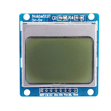
LCD Screen- Arduino Board (from left to right looking at the screen)
1 RST - digital pin 6
2 CE - digital pin 7
3 DC - digital pin 5
4 DIN - digital pin 4
5 CLK - digital pin 3
6 VCC - 5V
7 BL - VCC(on LCD)
8 GND - GND
For this one:
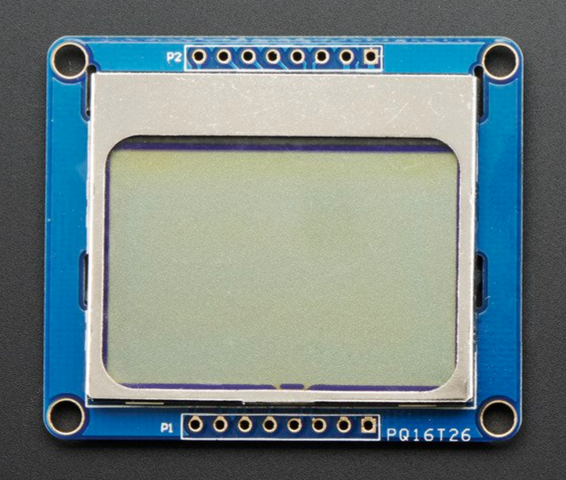
LCD Screen- Arduino Board (from right to left looking at the screen)
1 GND - GND
2 VCC - 5V
3 CLK - digital pin 3
4 DIN - digital pin 4
5 D/C - digital pin 5
6 CS - digital pin 7
7 RST - digital pin 6
8 LED - 5V
Code
This is an example that comes with the library PCD8544
/*
Copyright (c) 2010 Carlos Rodrigues <cefrodrigues@gmail.com>

 */


#include <PCD8544.h>
static PCD8544 lcd;


void setup() {
  // PCD8544-compatible displays may have a different resolution...
  lcd.begin(84, 48);
}


void loop() {
  // Just to show the program is alive...
  static int counter = 0;

  // Write a piece of text on the first line...
  lcd.setCursor(0, 0);
  lcd.print("Hello, World!");

  // Write the counter on the second line...
  lcd.setCursor(0, 1);
  lcd.print(counter, DEC);

  // Use a potentiometer to set the LCD contrast...
  // short level = map(analogRead(A0), 0, 1023, 0, 127);
  // lcd.setContrast(level);

  delay(200);
  counter++;
}
Input Output Examples
Input button, output LED
int LED1 = 13;
int butpin = 8;

void setup() {
  pinMode(butpin, INPUT_PULLUP);
  pinMode(LED1, OUTPUT);
  Serial.begin(9600);

}

void loop() {
  if (digitalRead(butpin) == LOW) {
    Serial.println("Button one is pressed!");
    digitalWrite(LED1, HIGH);
  }
  else {
    digitalWrite(LED1, LOW);
  }
}
Input Photoresistor, Output Neopixel
Input from photo resistor defining the intensity of red on the neopixel strip
#include <FastLED.h>

#define DATA_PIN 7 // Define the Digital pin your data pin is connected to
#define NUM_LEDS 10 //Define how many leds your strip has

CRGB leds[NUM_LEDS];


int lightPin = 0; //Define the Analog pin your photo resistor is connected to
int lightInt;
int lightMap;


void setup() {
  // put your setup code here, to run once:
  Serial.begin(9600);
  FastLED.addLeds<NEOPIXEL, DATA_PIN>(leds, NUM_LEDS);

}

void loop() {
  // put your main code here, to run repeatedly:
  lightInt = analogRead(lightPin);
  Serial.println(lightInt);

  lightMap = map(lightInt, 600, 1023, 0, 255);

  for (int i = 0; i < NUM_LEDS; i++) {

    leds[i] = CRGB(lightMap, 0, 0);
  }
  FastLED.show();

}
Input DHT11, Output LCD
Printing humidity and temperature in Nokia 5110
/*
  Copyright (c) 2010 Carlos Rodrigues <cefrodrigues@gmail.com>

*/

#include "DHT.h"

#include <PCD8544.h>
static PCD8544 lcd;

#define DHTPIN 8 //Define the pin your DHT is connected to
#define DHTTYPE DHT11
DHT dht(DHTPIN, DHTTYPE);

void setup() {
  // PCD8544-compatible displays may have a different resolution...
  lcd.begin(84, 48);
  dht.begin();
}


void loop() {
  // Just to show the program is alive...
  delay(2000);
  float h = dht.readHumidity();
  float t = dht.readTemperature();

   if (isnan(h) || isnan(t)) {
    Serial.println("Failed to read from DHT sensor!");
    return;
  }

  // Write a piece of text on the first line...
  lcd.setCursor(0, 0);
  lcd.print("Temp: ");
  lcd.print(t);
  lcd.println(" *C");
  lcd.setCursor(0, 1);
  lcd.print("Humid: ");
  lcd.print(h);
  lcd.print(" *C");


  // Use a potentiometer to set the LCD contrast...
  // short level = map(analogRead(A0), 0, 1023, 0, 127);
  // lcd.setContrast(level);


}