Automated Plant Watering System with soil moisture sensor
Here is a tutorial on how to build a basic plant-watering device using Arduino with some simple inputs and outputs.
This tutorial is written so that each of the components and their usage is explained and tested before being assembled into a whole device.
Components
- Adruino uno
- Soil moisture sensor (bought or homemade)
- Nokia 5110 LCD display
- Peristaltic pump
- L298N H-bridge motor shield
Arduino
Arduino is an open-source electronics platform that is used to sense the real world, make interactive projects and prototypes.
The Arduino board is able to read inputs and write outputs. In this example, the input will be a soil moisture sensor and the outputs will be an LCD screen and a peristaltic pump, which is a simple continuous DC motor. Using code, we can control how the input affects the output.
Download the Arduino software here. This is used to program the Arduino microcontroller. Thereafter, the program is in the Arduino, and will continue to run without the computer present.
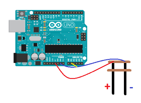
Soil moisture sensor
The sensor here is essentially two electrodes with a space in between, where the resistance varies depending on how much moisture the soil contains (higher moisture content = lower resistance). While this does not give us the absolute value of the soil moisture content due to variables such as temperature and ion content, for example, it does give a decent approximation.
This sensor then sends an analogue input signal to the Arduino.
Wiring:
5V -> (+) electrode
GND -> (-) electrode
A1 -> (-) electrode
 Example code:
#define sensorpin A1

//creating integers
int moisture;
int moisturepercent;

void setup() {
  // put your setup code here, to run once:

  //begin serial monitoring
  Serial.begin(9600);
}

void loop() {
  // put your main code here, to run repeatedly:
moisture = analogRead(sensorpin); // Read moisture sensor value
moisturepercent= map(moisture, 0, 1023, 0, 100); //changing to percent
Serial.println(moisturepercent);//show serial monitor values
}
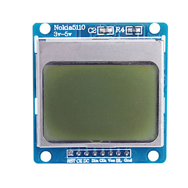
Nokia 5110 LCD Screen
You've seen it on Grandma's phone, now you can use it for something other than playing Snake.
First you need to include the library used by Arduino to manage this component. Go to: "menu->sketch->include library->manage libraries" and find 'PCD8544 by Carlos Rodrigues'
 Wiring (for this you will need a breadboard):
LCD Screen- Arduino Board (from left to right looking at the screen)
1 RST - digital pin 6
2 CE - digital pin 7
3 DC - digital pin 5
4 DIN - digital pin 4
5 CLK - digital pin 3
6 VCC - 5V
7 BL - VCC(on LCD)
8 GND - GND
Example code:
/*
Copyright (c) 2010 Carlos Rodrigues <cefrodrigues@gmail.com>

 */


#include <PCD8544.h>
static PCD8544 lcd;


void setup() {
  // PCD8544-compatible displays may have a different resolution...
  lcd.begin(84, 48);
}


void loop() {
  // Just to show the program is alive...
  static int counter = 0;

  // Write a piece of text on the first line...
  lcd.setCursor(0, 0);
  lcd.print("Hello, World!");

  // Write the counter on the second line...
  lcd.setCursor(0, 1);
  lcd.print(counter, DEC);

  // Use a potentiometer to set the LCD contrast...
  // short level = map(analogRead(A0), 0, 1023, 0, 127);
  // lcd.setContrast(level);

  delay(200);
  counter++;
}
Now try use it to print the moisture percent values.
Pump and motor shield
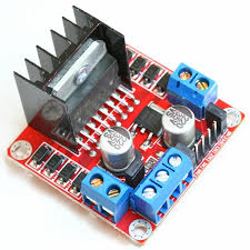 Now comes the electronics side of things. Because the pump requires more power than we can provide through the Arduino without damaging it, we need to use an external power supply matching the voltage required by the pump, and use the digital pins of the arduino to turn it on or off.
Here this is done using an L288N H-Bridge DC motor driver, which can take inputs from 5V-35V and current of up to 2A (One must disconnect the jumpers that supply power to the components of the H-bridge itself if >12V is used, but we won't deal with that here).
Wiring:
Positive wire (live) of power supply to +5V/+12V on H-Bridge.
Negative wire (neutral) of power supply to ground.
Digital pin 8 (Arduino) to in1 (H-Bridge)
Digital Pin 9 to in2 (H-Bridge)
Both wires from pump to Output A (H-Bridge)
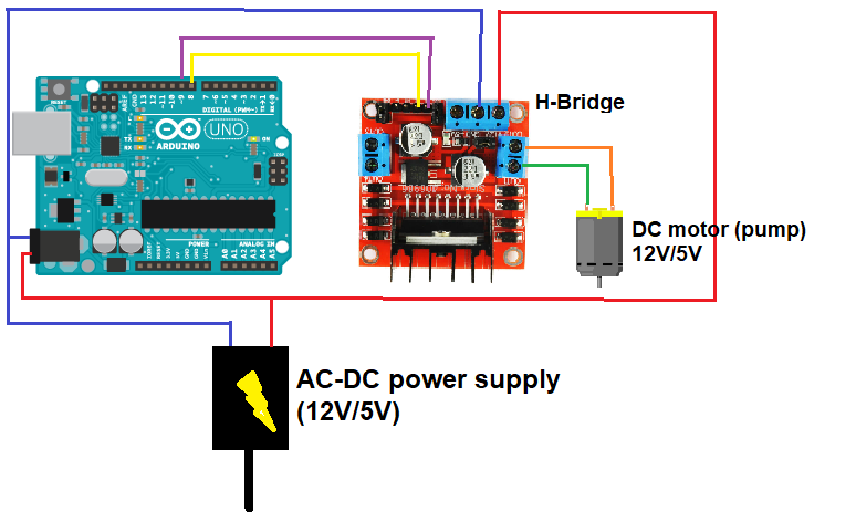
Note: there are different power supply inputs on the H-bridge for 12V and 5V. There should be labels on the H-bridge stating which is which.
Code:
//defining pins
#define in1 8
#define in2 9
#define sensorpin A1
//creating integers
int moisture;
int moisturepercent;

void setup() {
  //configure digital pins to OUTPUT
  pinMode(in1, OUTPUT);
  pinMode(in2, OUTPUT);

  // Set initial rotation direction of motor
  digitalWrite(in1, LOW);
  digitalWrite(in2, HIGH);

}
void loop() {
moisture = analogRead(sensorpin); // Read moisture sensor value
  moisturepercent= map(moisture, 0, 1023, 0, 100);

//activating the motor if moisture is below 20%
if(moisturepercent < 20)
{
digitalWrite(in1, LOW);
digitalWrite(in2, HIGH);
}
else if (moisturepercent > 20)
{
 digitalWrite(in1, LOW);
 digitalWrite(in2, LOW);
}
}
Challenges
Here are some tips/hints on how you might improve the design of your system:
- The H-bridge
As you may have figured, this component is slightly overkill for such simple requirements as we have in this project. It has the capacity for controlling speed as well as on/off functionality and switching current direction. It can also be used to control TWO motors at once, which could be useful if you want to build a setup that takes care of two plants instead of one (hooray for maximum efficiency). This can be added onto the current setup simply by utilizing the other input pins and output ports on the H-bridge in the same way as we did with the first motor, and adding the corresponding code.
For more info on the driver: https://howtomechatronics.com/tutorials/arduino/arduino-dc-motor-control-tutorial-l298n-pwm-h-bridge/
Alternatively, a simpler (and cheaper) relay could be used in place of the H-bridge.
- Solving the corrosion problem:
The issue with running a DC current through a set of electrodes in a moist environment over a long period of time is that eventually they begin to corrode and become useless.
One way to solve this is to set Arduino to only read the sensor (and power it) once every set period of time. This can be achieved with the millis/delay function and powering the sensor with a digital pin rather than +5V.
How to use the millis function: https://www.arduino.cc/en/tutorial/BlinkWithoutDelay
OR
See if you can find a way to alternate the direction of the current to the sensor using the digital pins!