Make a robotplatform
Fablab friendly and hackable robot - source codes and diagrams.
By: Mads Hobye, Nikolaj Møbius and Nicolas Padfield
Please credit FabLab RUC and illutron art collective
http://ruc.dk/fablab http://illutron.dk
This project is licensed under: CC BY-SA
Our robotics platform has been used in several workshops for high school and university students. Participants built a robot, gave it personality and experimented with the interaction between humans and technology. We provided laser cut robot parts, the Arduino open source rapid prototyping platform, electronics and programming building blocks. A single distance sensor and different behaviours coded as modular functions allow a range of behaviours to be combined. We provide the participants the possibility to think, experiment and express themselves through the material, the media of the behaviours, look and feel of a robot - rather than more well known, established media such as a film or a written report. Expression through the material itself, not through words in a pamphlet about it. The material is the media, we think through the material, the material is primary.
Components needed:
- Arduino board *Servo controller shield or prototyping shield (or other means to connect the servo)
- Power supply *Usb cable
- 4mm HDF material
- 4 Servos
- About 200 micro farad capacitor.
- Infrared distance sensor
Guide:
1. Download the below elements:
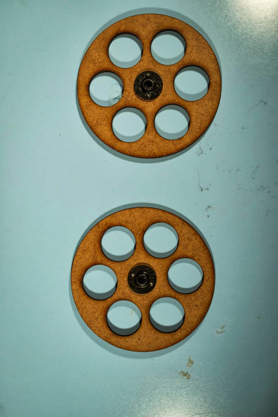
2. Laser cut the vector drawing in 4mm HDF
The settings depend on the laser. For a 100 watt laser cutter:
- Cut speed: 15 mm/s.
- Cut power: 100 watt.
- Corner power: 80 watt.
The vector files include components for different types of the robot. E.g. for line following functions and for a rubber band shooter. You will not need every component to build the basic version.
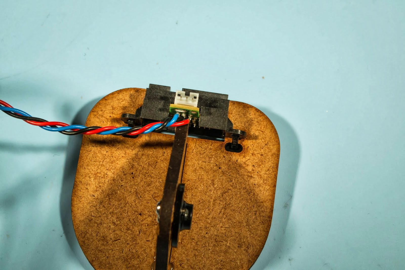
3. Make circuit for the four servos
The four servos should be connected in a similar fashion as the diagram below. It is advised to place a capacitor (at least/approximately 200 micro farad - exact value is not critical) between plus and minus (plus on the capacitor should be connected to plus/5V on the Arduino).
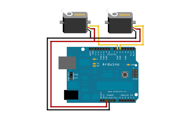
The servos should be connected to the following pins:
- left_motor: 6
- right_motor: 7
- neck_up: 8
- neck_turn: 9
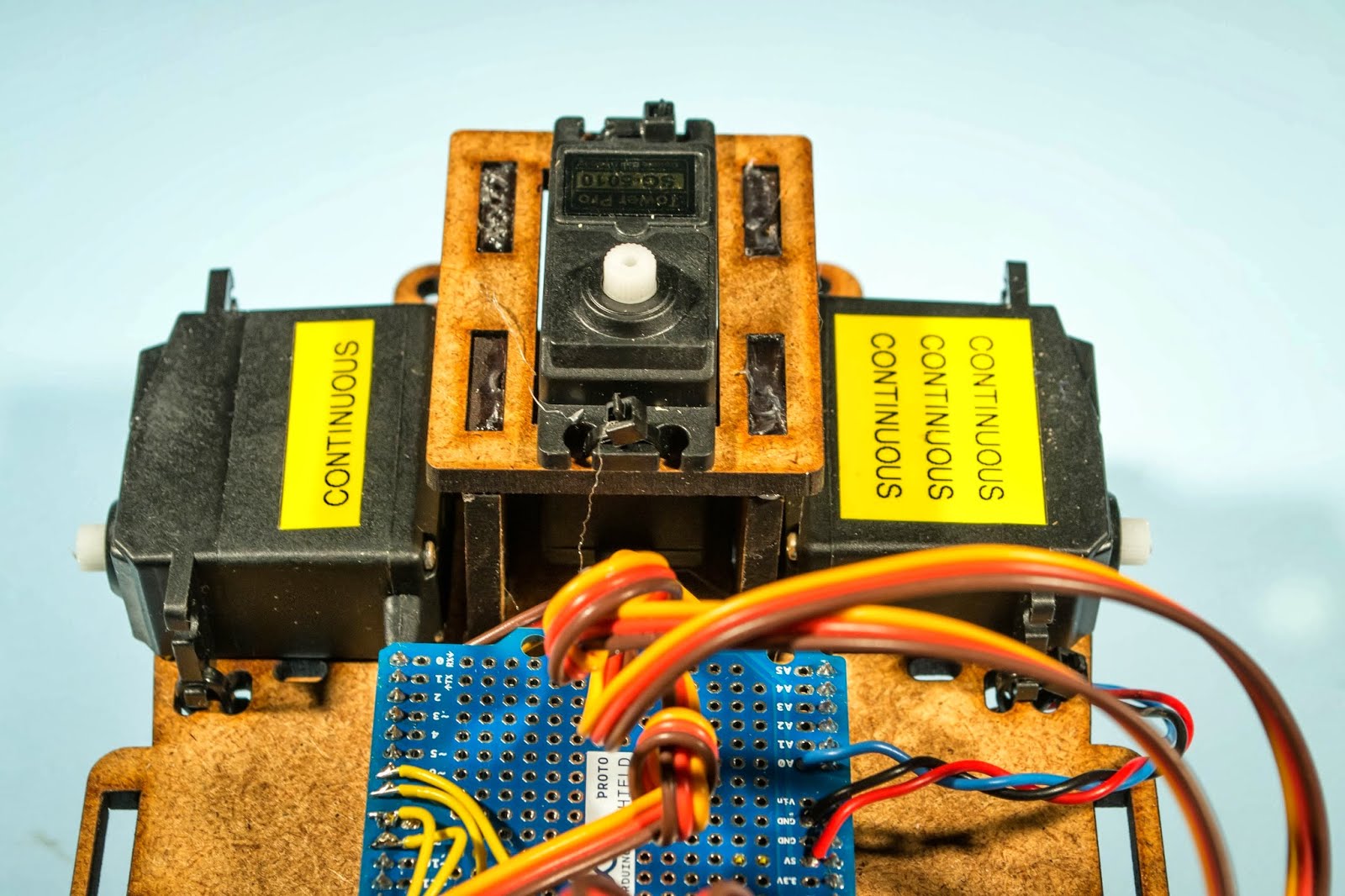
4. Turn the wheel servos into continuous servos
The servos used for the wheels should be converted into continuous rotation. You can find a tutorial on how to do it here:
https://learn.adafruit.com/modifying-servos-for-continuous-rotation/overview
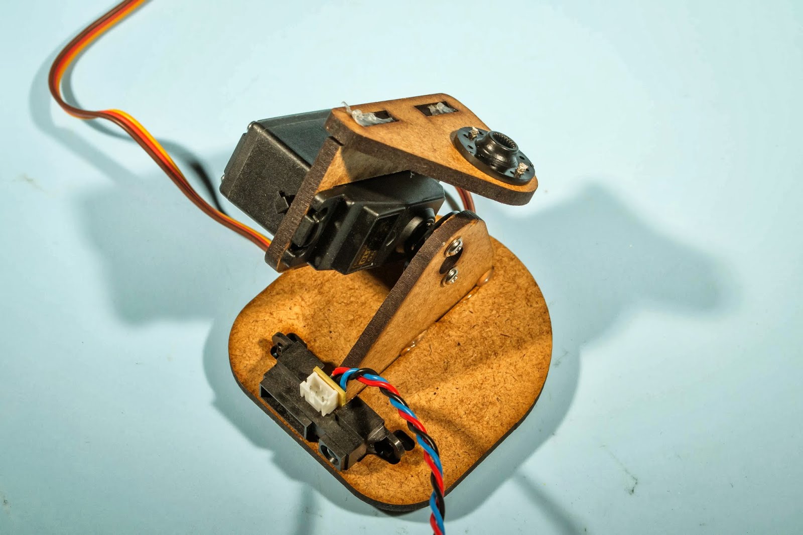
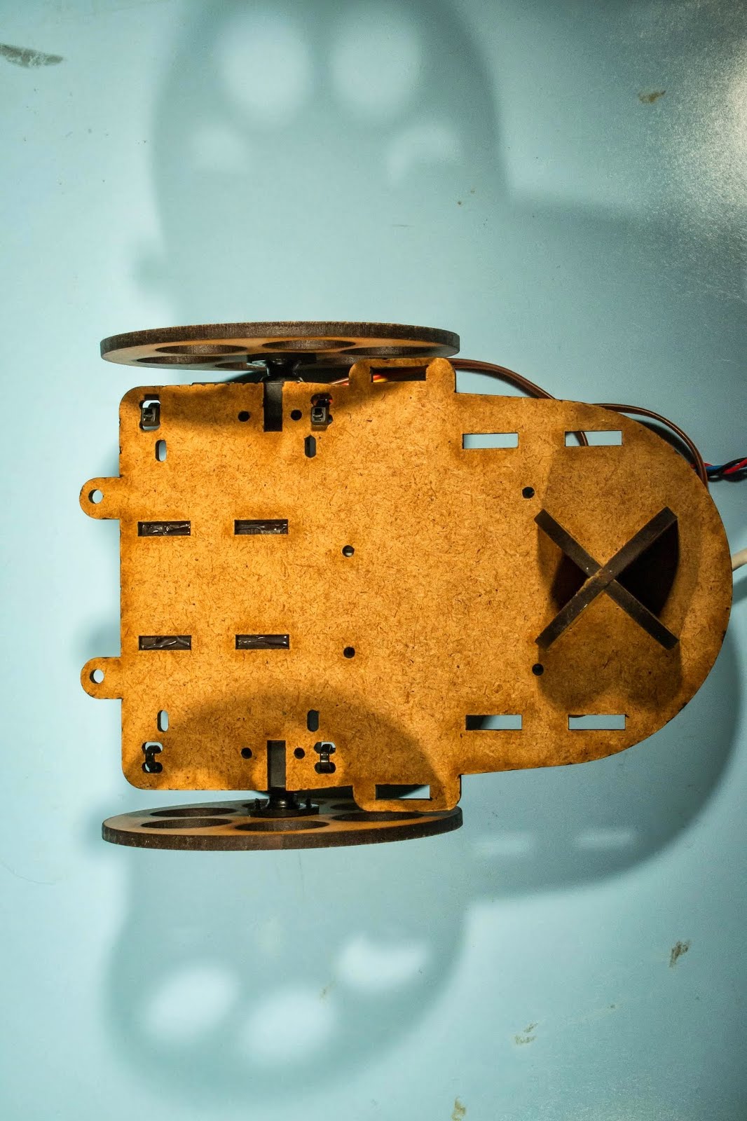
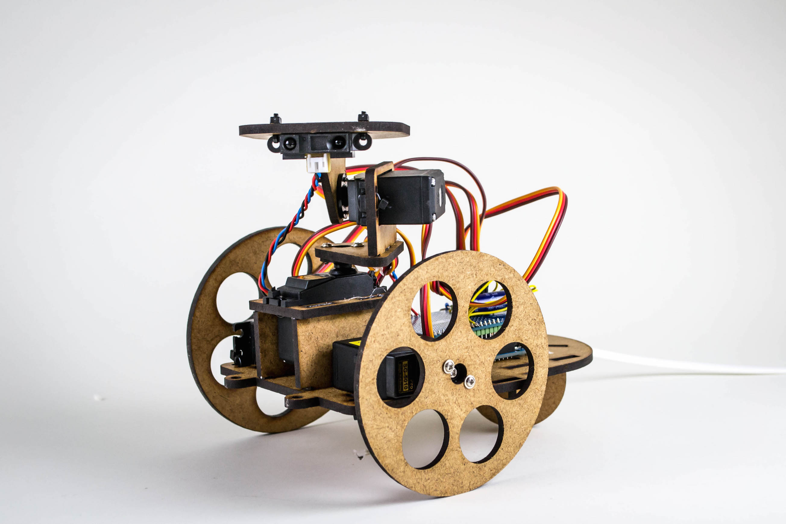
5. Assemble the parts
A more detailed guide will be published - until then we recommend one looks at the images below.
6. Upload the code
The code should be uploaded through the Arduino interface. Here are the simple steps:
- Go into the folder “animismbotserial” and open “animismbotserial.ino”.
- Choose the proper serial port your Arduino is connected to. Press upload (play button).
The wheels mix turn slowly depending on how well the continuous mode was adjusted. To fix this adjust the calibration values in the top:
int servos_calibration[] = {
  90,90,90,90}; // used for continuous rotation to calibrate center point
The first value defines center point for the left motor and the second for the right motor.
An alternative version exists in the dropbox folder. This version uses guino as its interface. Read more about guino here: http://www.instructables.com/id/Guino-Dashboard-for-your-Arduino/
Detailed photos