Plastic Recycling Shredder
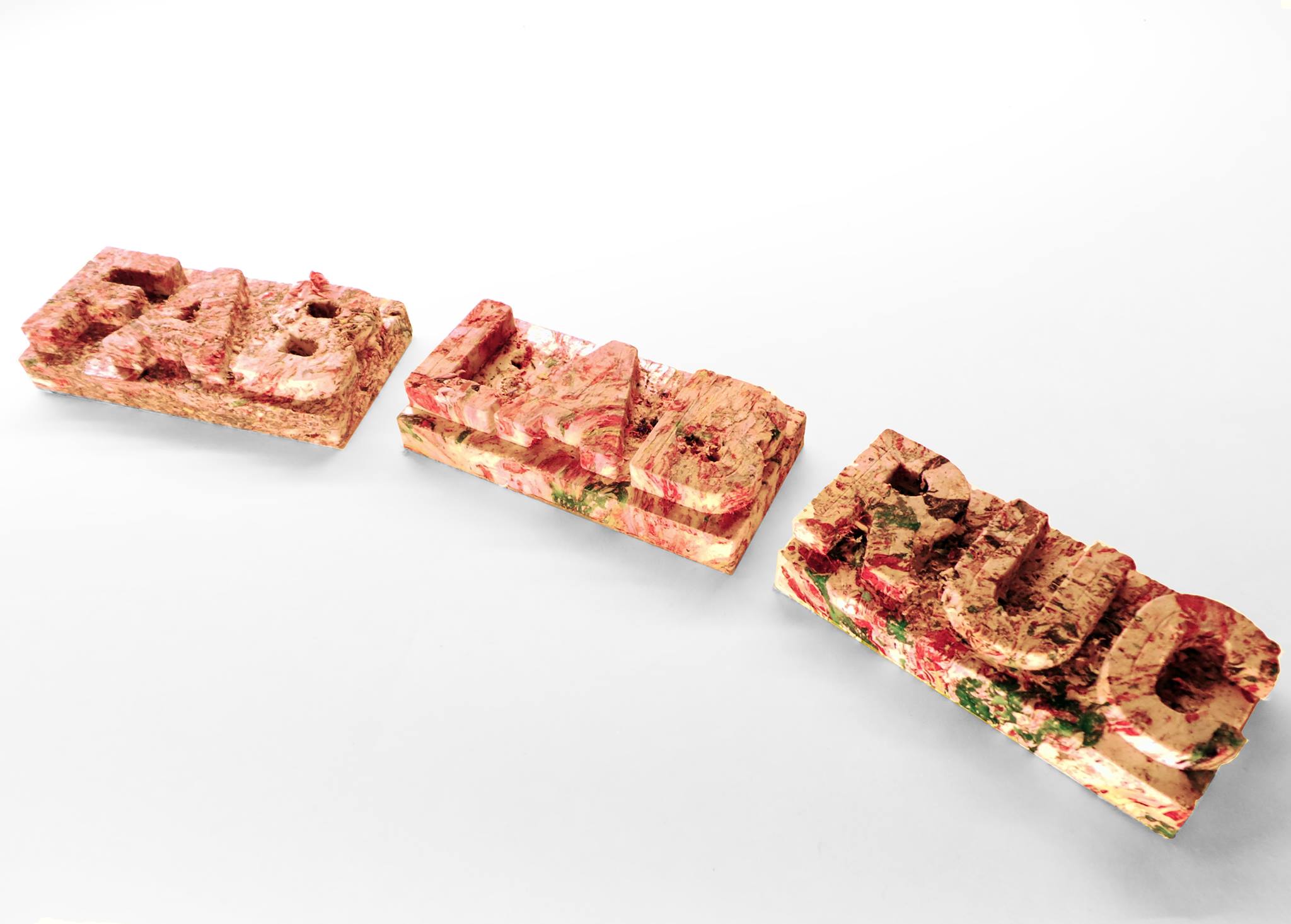
This tutorial provides instructions on how to build a shredder capable of shredding sheet plastics, such as HDPE and LDPE, found in plastic bags, bubble wrap and air cushion packaging, to prepare it for recycling. The machine is part of a greater project to develop a process of turning waste HDPE/LDPE into a useable material. HDPE and LDPE both have a very low melting point of 130°C and 100°C respectively. This means that they can easily be melted and formed into useable material, to maximise the structural integrity and density of the material it is required to shred it down into thin straw like strands.

What You will Need

Available as .pdf format in Plastic Shredder folder
The motor will be very expensive, try searching scrap yards or looking on confidential advertisements to find one. Bear in mind you need incredibly high amounts of torque but not much speed so a geared motor will work best. If your motor has a high speed then you will need to adjust the gear ratio between the drive shaft and the axle by using the gear generator software to create your own custom gears.
Instructions:
Part 1: Blades and Housing
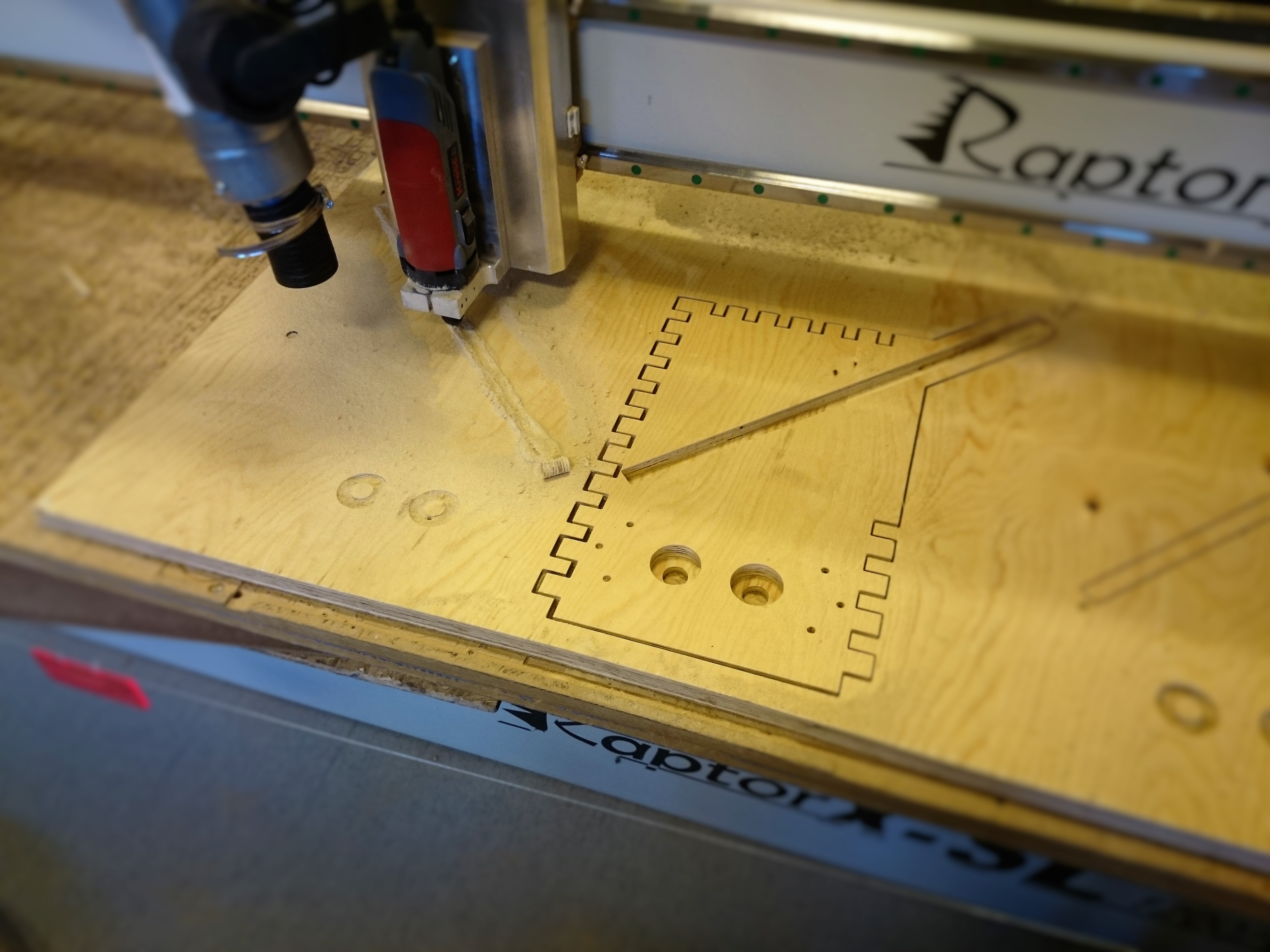
The first stage of building the shredder is cutting and assembling the housing. The housing is cut from 18mm Ply using a CNC machine. For specific instructions of how to use a CNC machine Click Here. A file containing the tool path for a 3mm diameter tool can be found in the drawings folder named “Housing 3mm CNC Tool Path”. Alternatively if you would like to generate your own tool path the original drawing can be found in the file named “Drawings Complete”
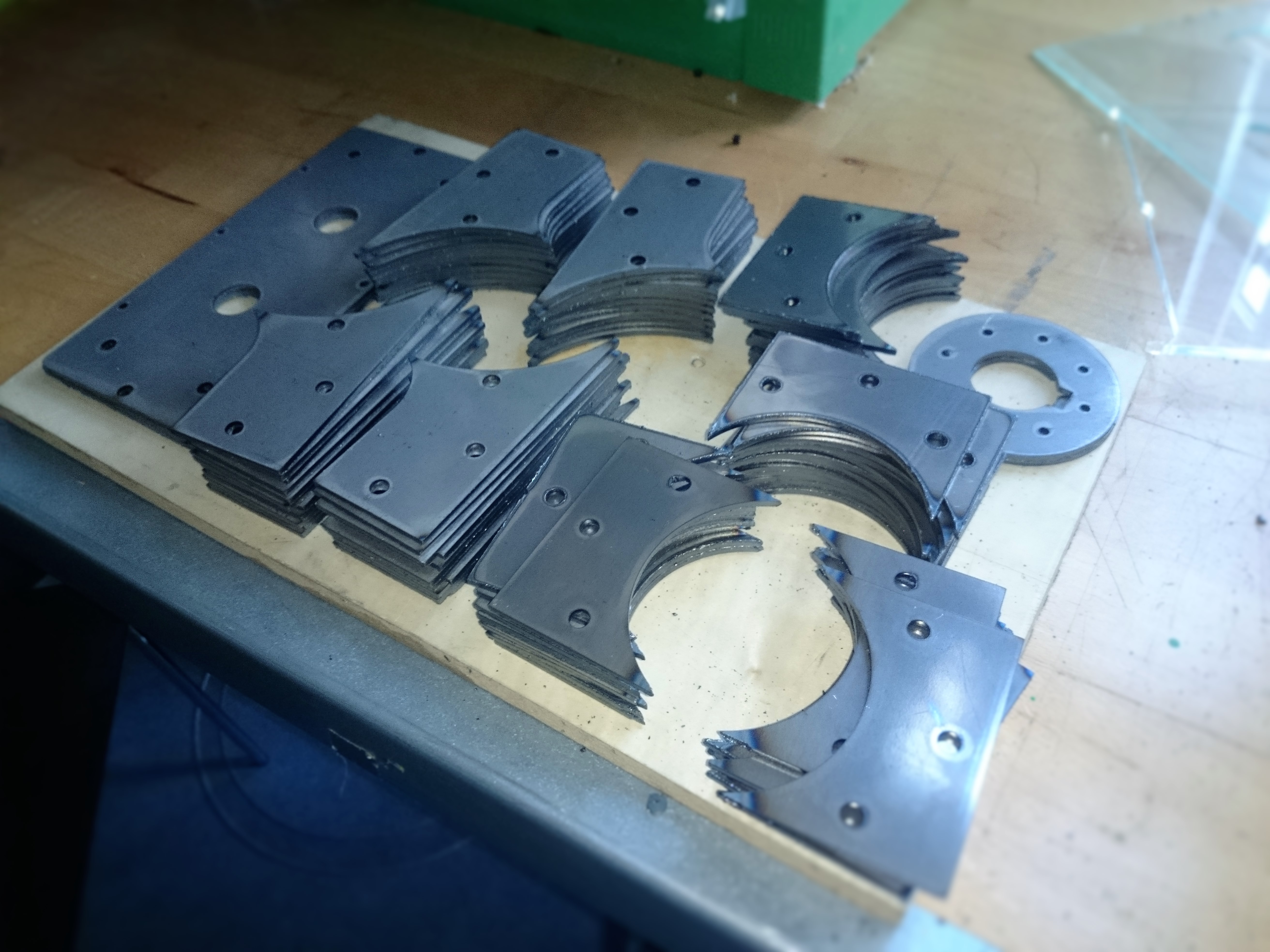
The teeth and spacers are cut from 4mm steel. A file containing the cutting path can be found in the drawings folder named “Steel Cutting Path”. There are several methods which can be used to cut the steel components e.g. a plasma cutting or water jet cutting. The machines are very dangerous to operate so unless you are trained to do so consult a specialist to help you. Try contacting a local FabLab or using a metal cutting service to product the parts for you.
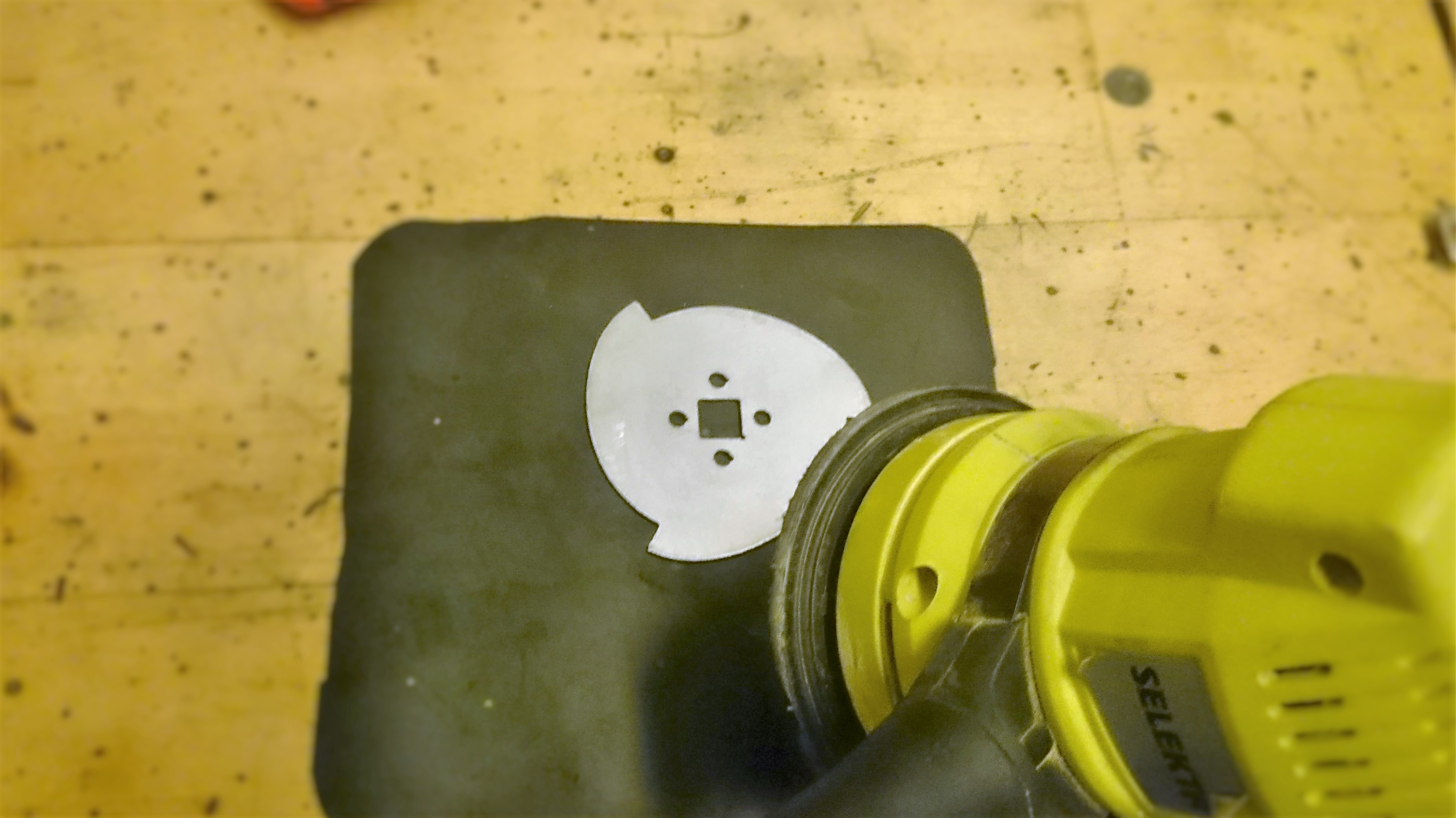
If there are any burred edges left from machining the plates it is important to sand them so that the machine runs smoothly. Use a rotary sander with 40 grit sandpaper to flatten each plate. Placing a sheet of rubber underneath the plate will stop it from sliding as you sand.
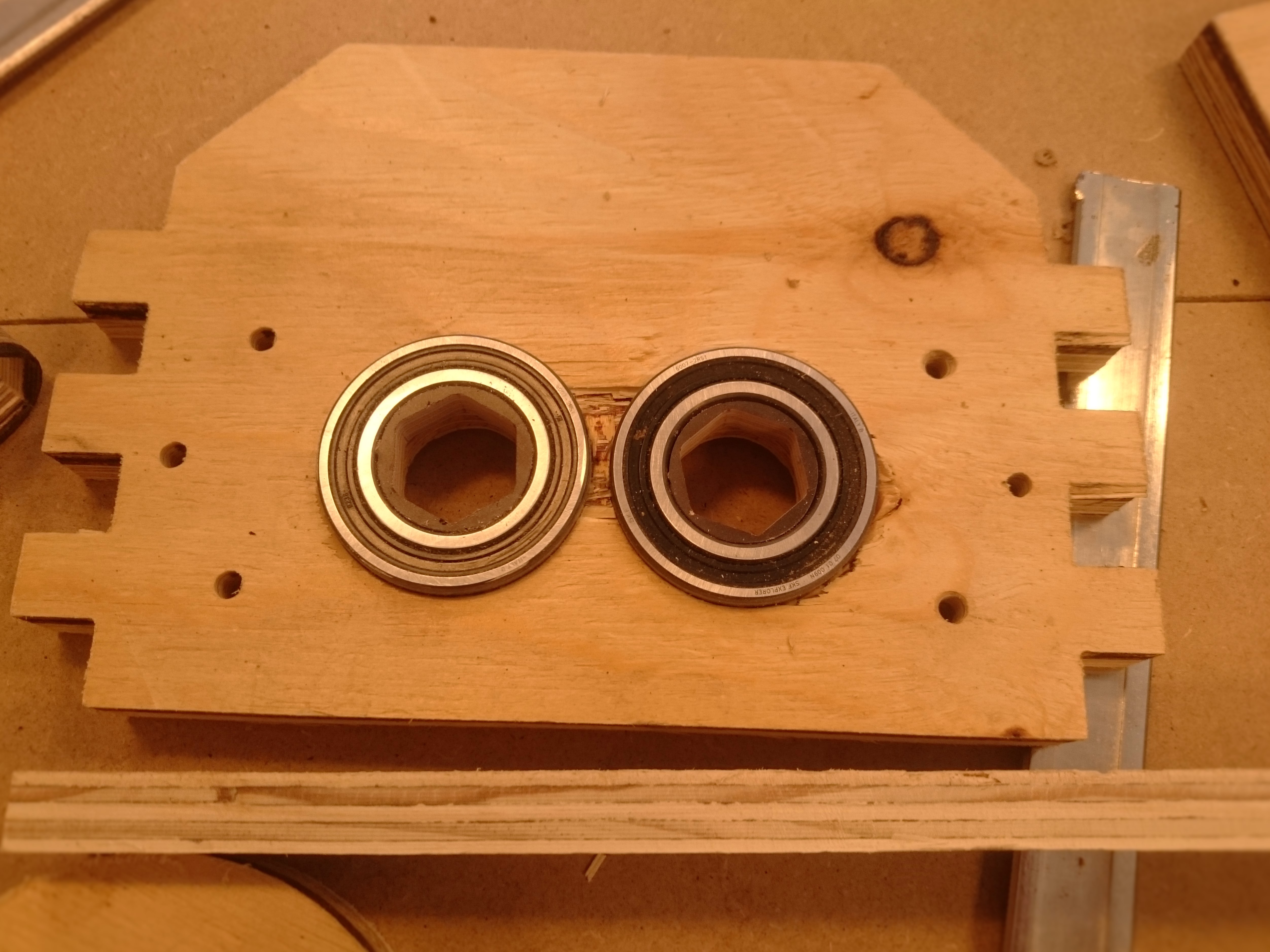
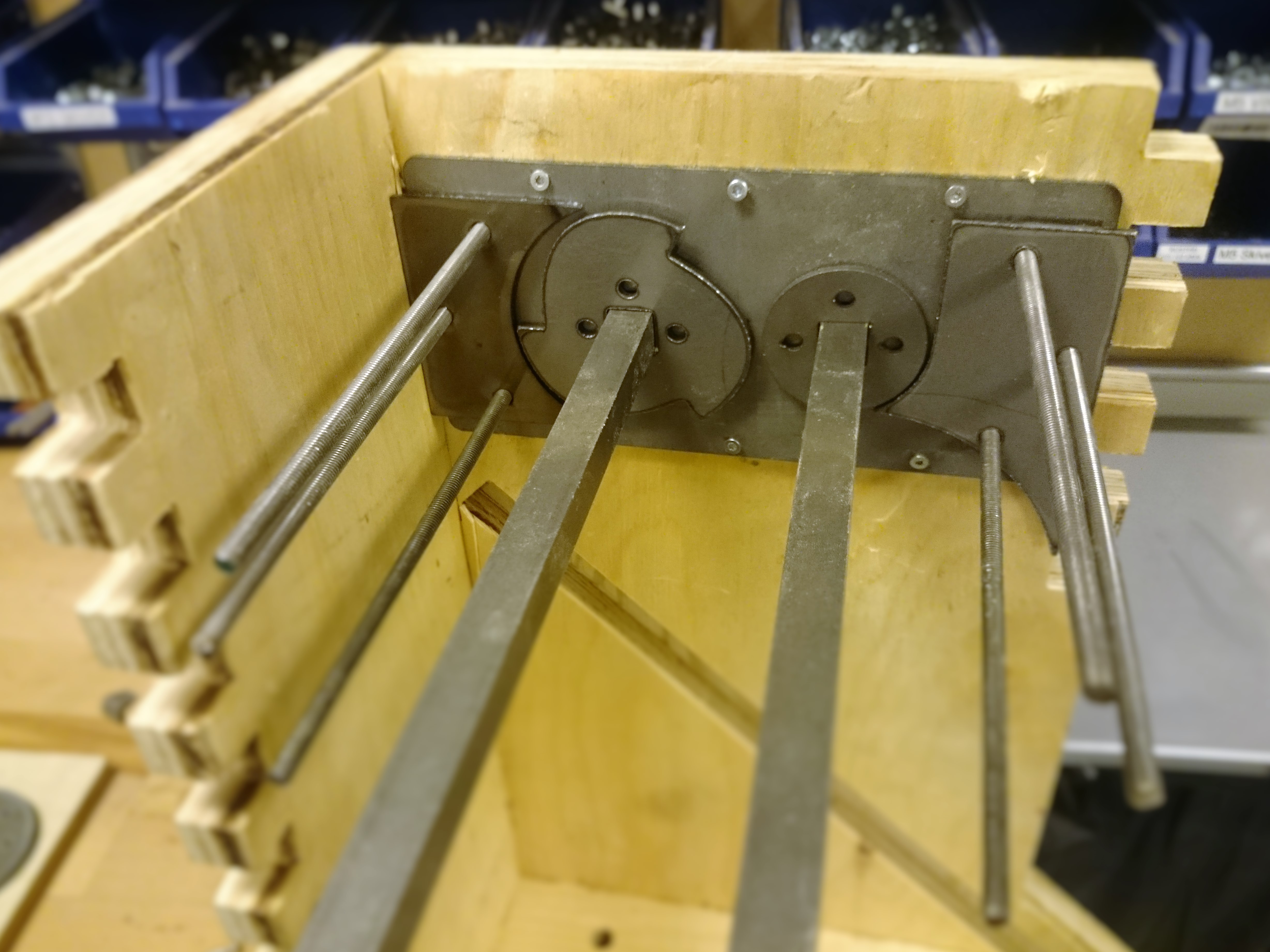
Using a soft mallet and a piece of scrap wood to protect the housing, hammer the four bearings in to the cavities of the piece pictured above. Apply glue to wood surrounding the bearings then align the corresponding wall section so that the two bearing holes and the six smaller holes surrounding them line up and hammer in to place.
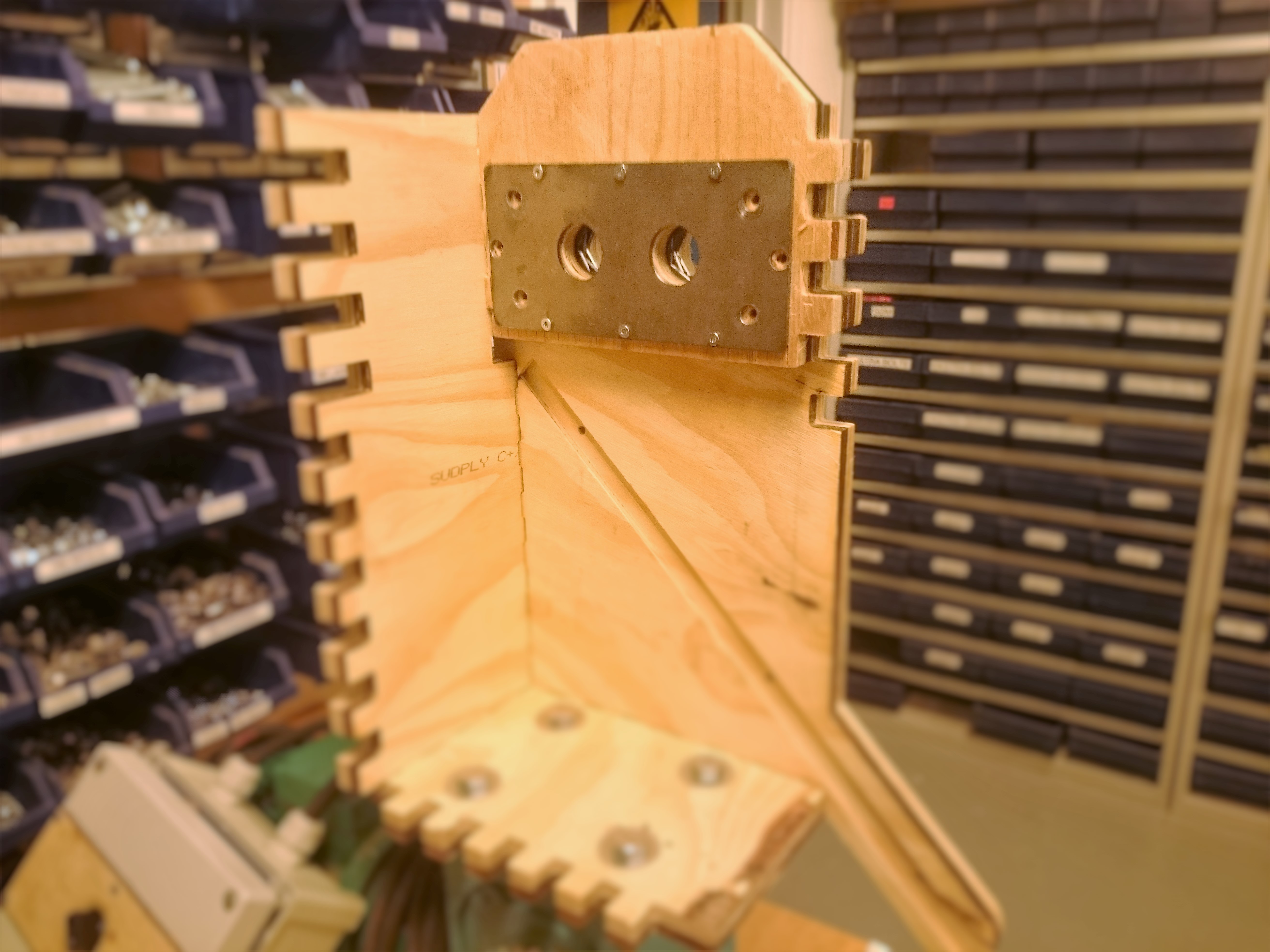
Position one of the rectangular plates on the inside of the body. Secure the plates in place using 5x20mm screws ensuring that the holes for the axle and surrounding the baring line up.
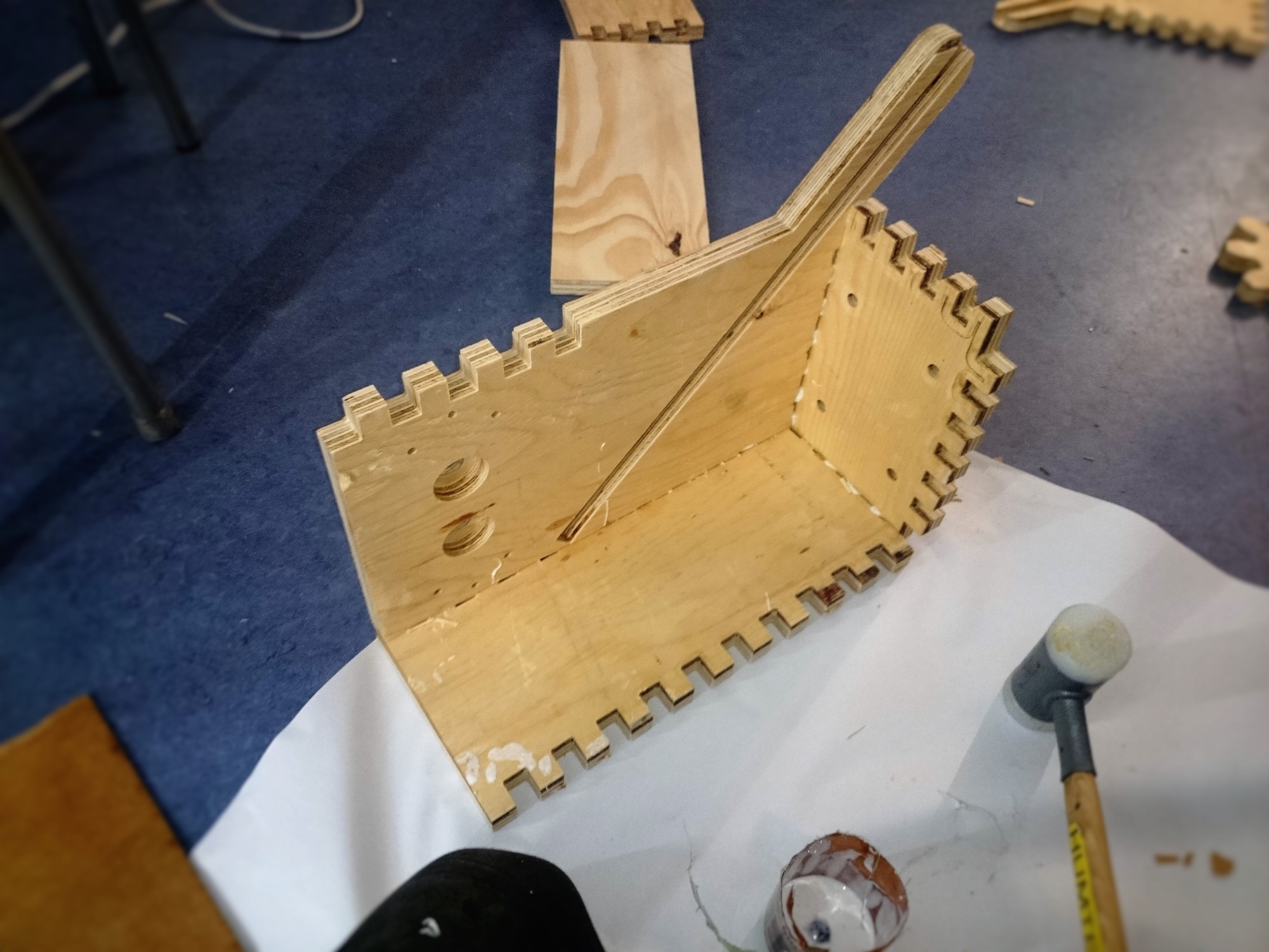
Next take the four sides (pictured above) and apply wood glue to the overlapping fingers. Using a soft mallet and a piece of scrap wood to protect the body, hammer the three faces in to place using a set square to ensure the faces are at a right angle.
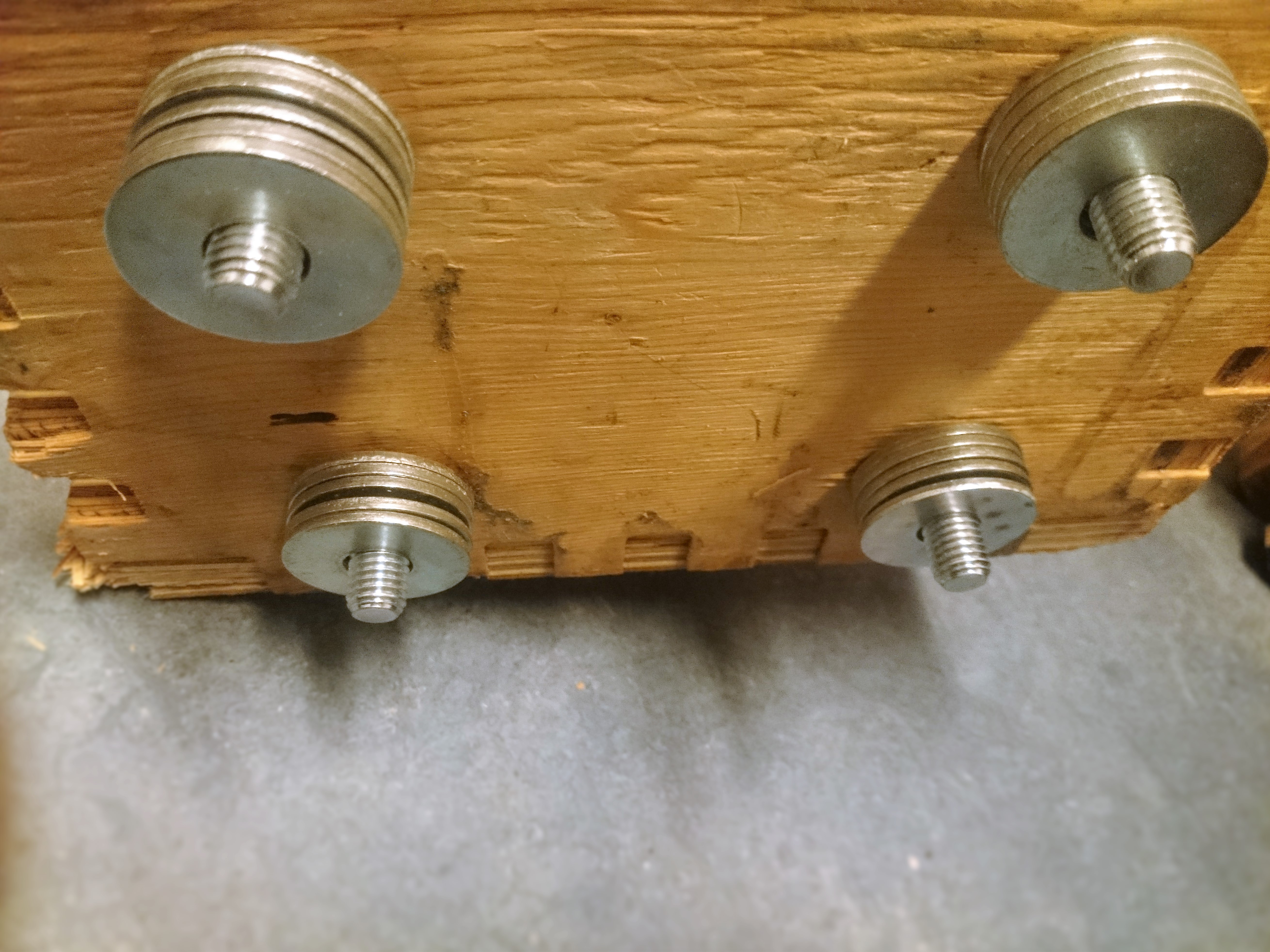
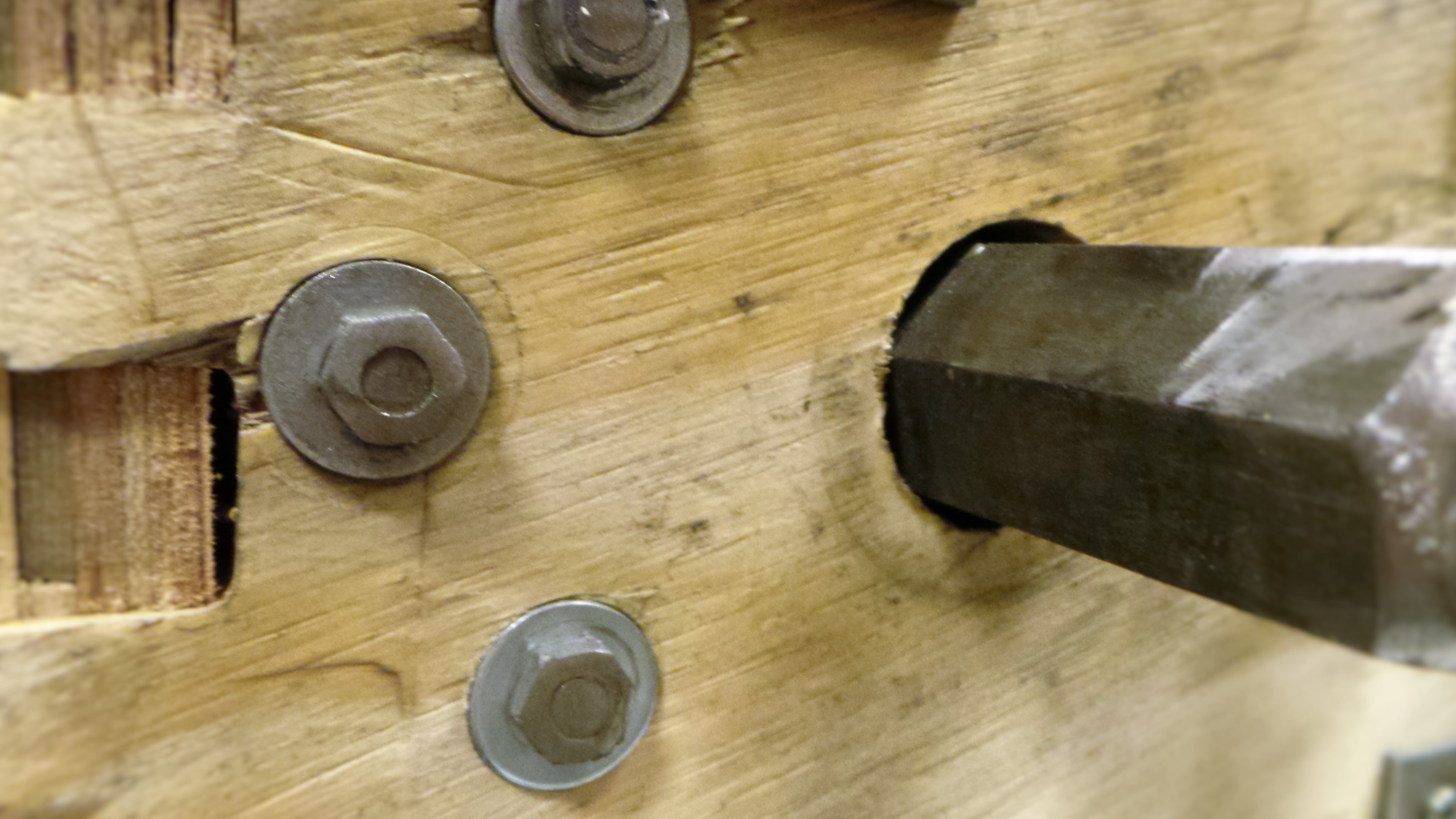
Take four M12x40mm bolts and insert them in to the holes in the bottom face of the housing with one M12 washer between the head of the bolt and the wood. Then insert 5 M12 washers on to each of the bolts before tightening the bolt in to the motor. If your motor has a different mounting arrangements adjust the drawing so that the holes align properly. Use a toque wrench to tighten the bolts securely.
To mount the main body of the shredder to the base plate flip the current assembly so that the holes of the underside of the motor face upwards. Insert an M12x100mm bolt and washer in to each hole then slide on the four supporting plates. Use a torque wrench to tighten the bolts the flip the assembly back so that it stands upright again.
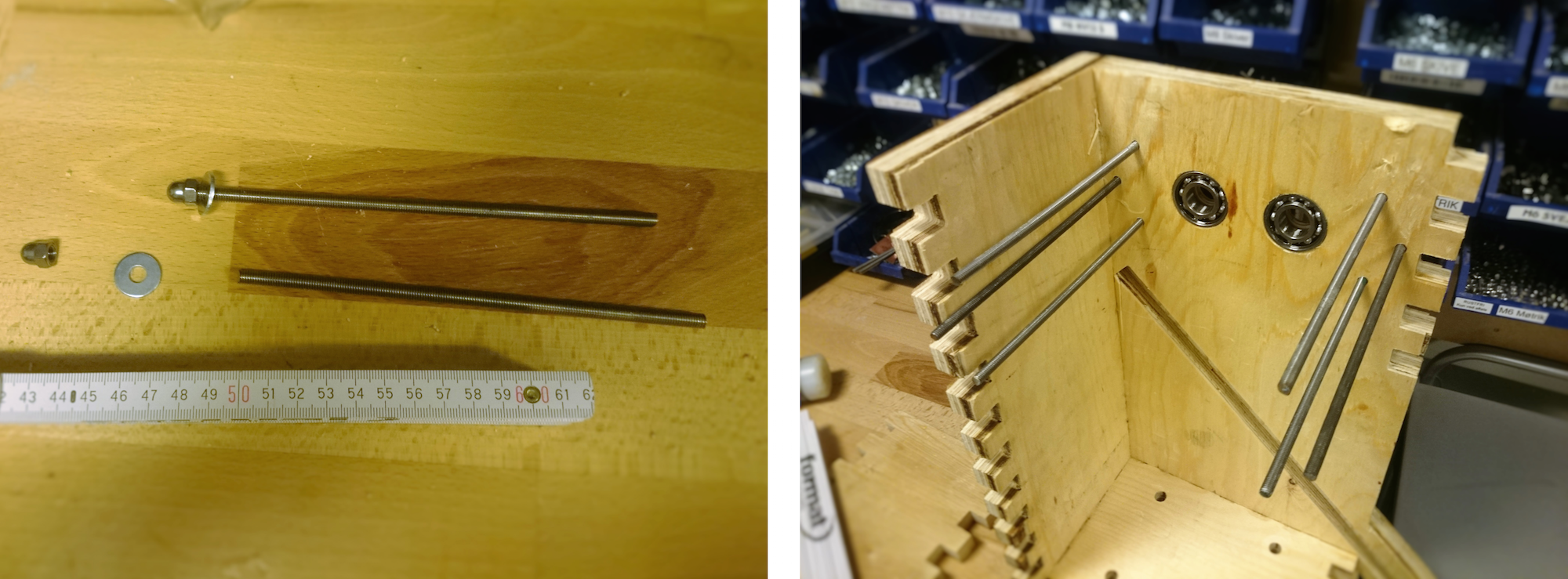
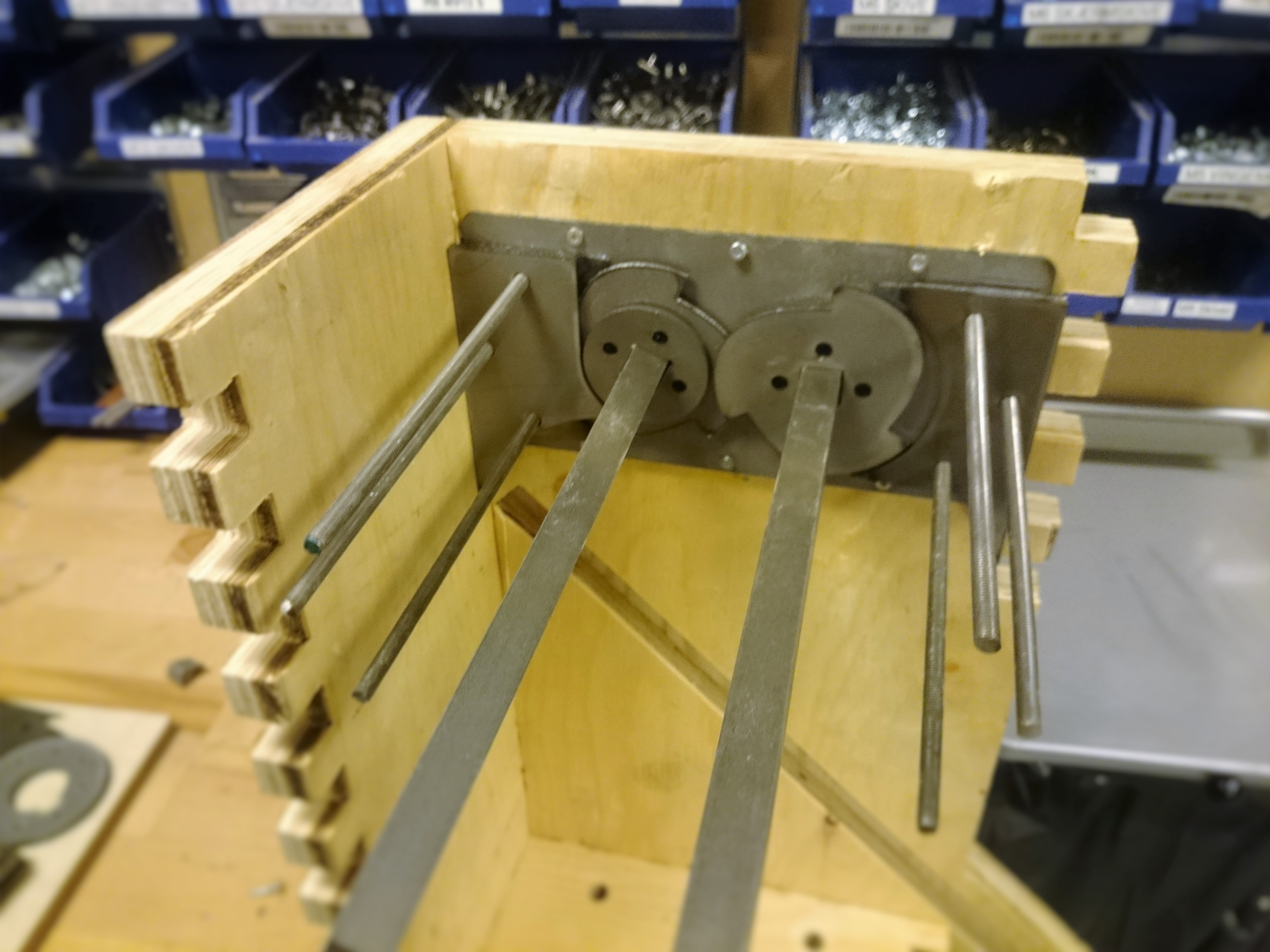
Using an angle grinder cut six lengths of M6 Threaded rod. Attach a M6 washer and lock nut to one end of each rod. Insert the rods in to the holes surrounding the bearings with the acorn nut outside of the housing. Also using an angle grinder cut two 300mm lengths of hexagonal axle and insert them through the bearings so that they sit with the bearings roughly in the middle.
Slide the teeth and spacers on to the axles and threaded rods like the arrangement pictured above. Make sure to place the tooth plate so that the teeth are facing inwards.
For the next layer the position of each plate is flipped so that the tooth plate is on the opposite axle like the arrangement pictured above. The tooth plate should also be rotated so that the teeth are at a 60° to the previous plate. This ensures that the teeth are spread as evenly as possible along the axle to distribute the force of shredding.
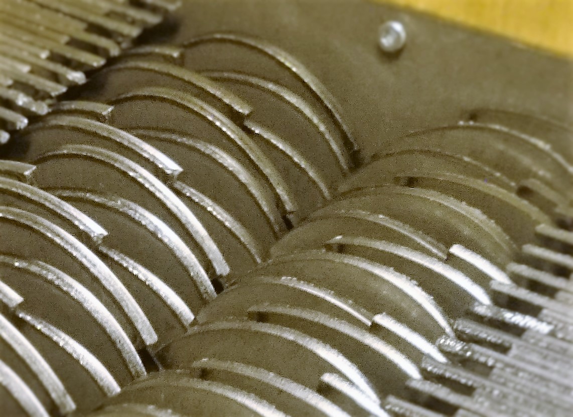
Repeat the pattern, flipping and rotating the teeth until all 25 layers, sliding the axle further through the bearings when required.
Take the opposite face side which houses the bearings and align the finger joints and apply glue, ensuring that the axle and threaded rods line up with their corresponding holes. Using a soft mallet and a piece of scrap wood to protect the body, hammer the face in to place.
Attach a M6 washer and lock nut to the ends of the M6 threaded rod. Use a torque wrench to tighten the nuts then cut of any excess thread using an angle grinder.
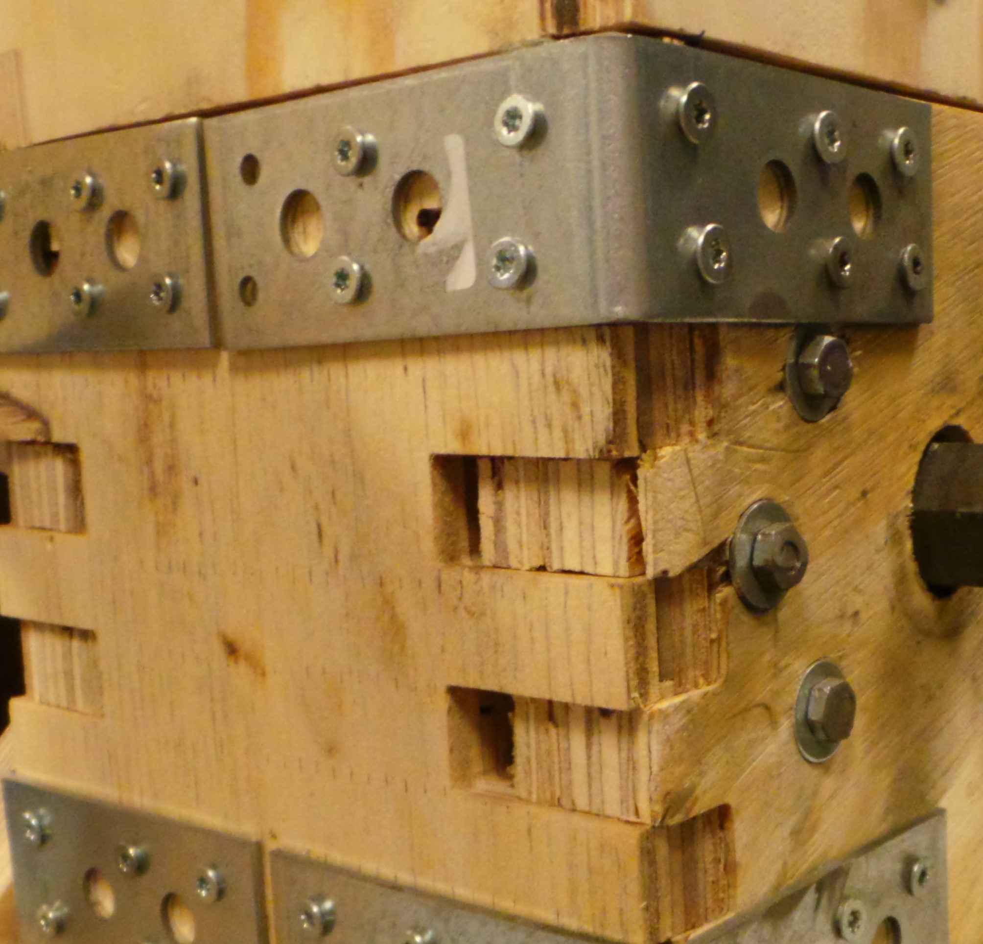
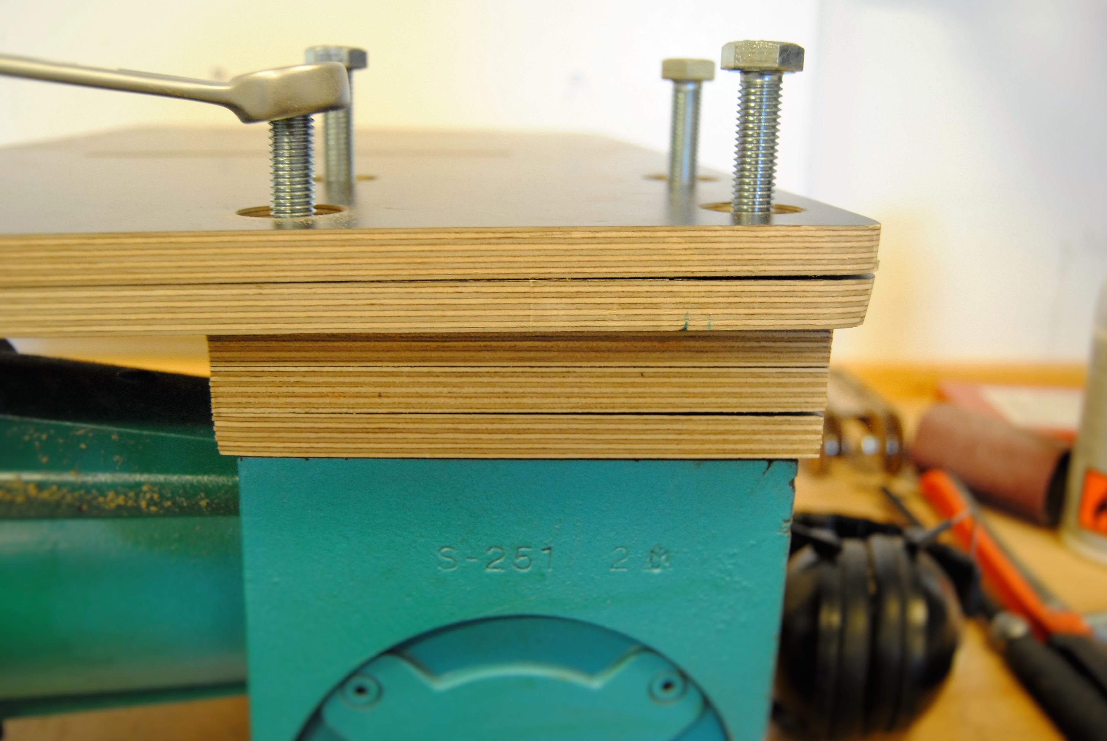
Using a soft mallet and a piece of scrap wood to protect the body, hammer in the final side of the housing. Attach L brackets to the four corners of the face using 5x20 screws. Mirror the brackets on the opposite side of the shredder.
Insert the exit ramp in to the two groves inside of the body. Drill a 6.5x200mm with a M6 washer in to the six holes along each face to secure it in place.
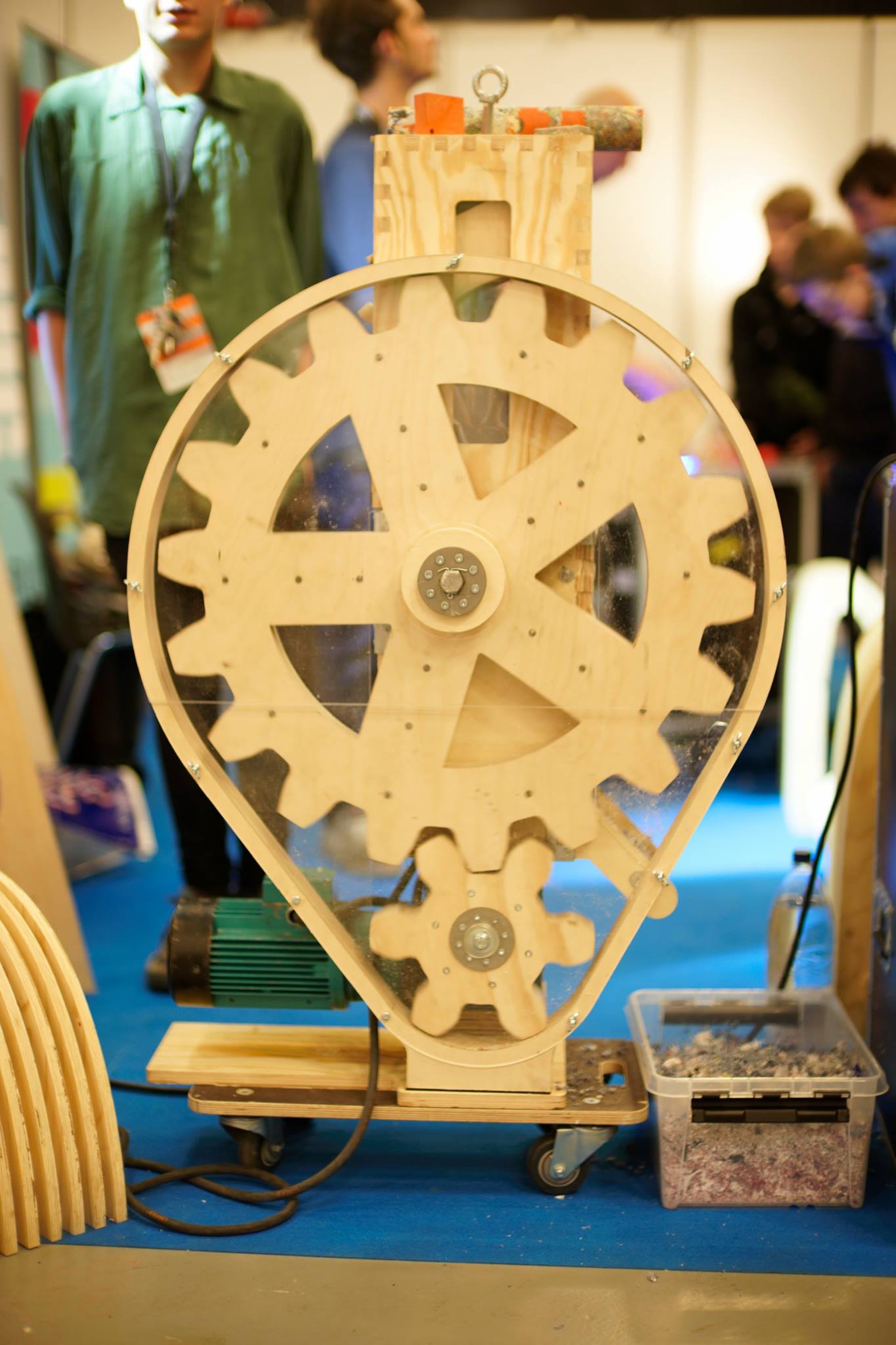
Part 2: Gears
To draw the gears I used the program Gear Generator available here. If you use a different motor, use the software to generate your own template by measuring the distance between the axle and the driveshaft, the ratio is 3:1. Make sure add enough bolt holes to secure the layers together.
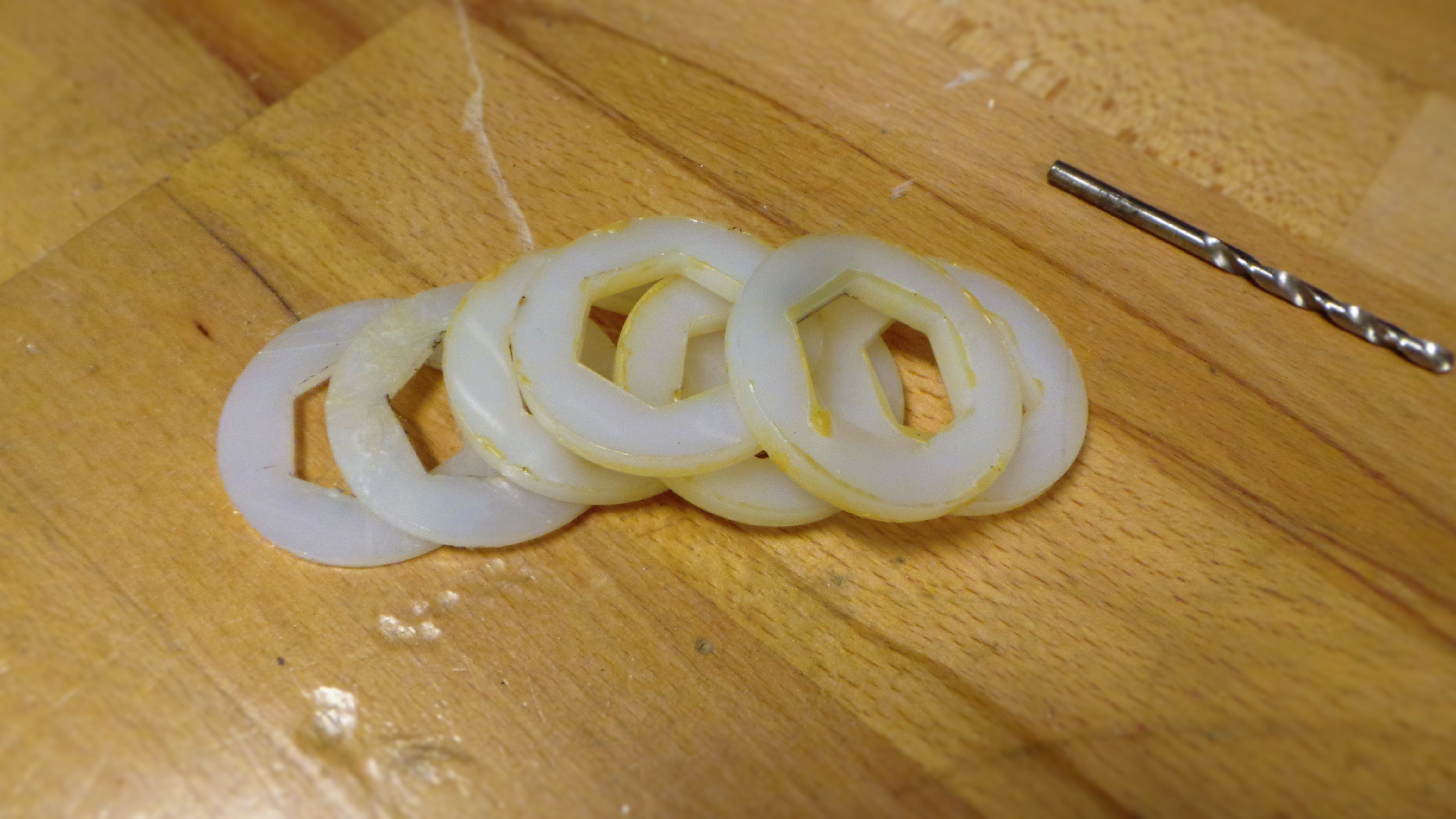
Before attaching the gears, nylon washers must be cut using a laser cutter. A file containing the cutting path can be found in the drawings folder named “Nylon Washers Cutting Path”. For specific instructions of how to use a laser cutter Click Here.
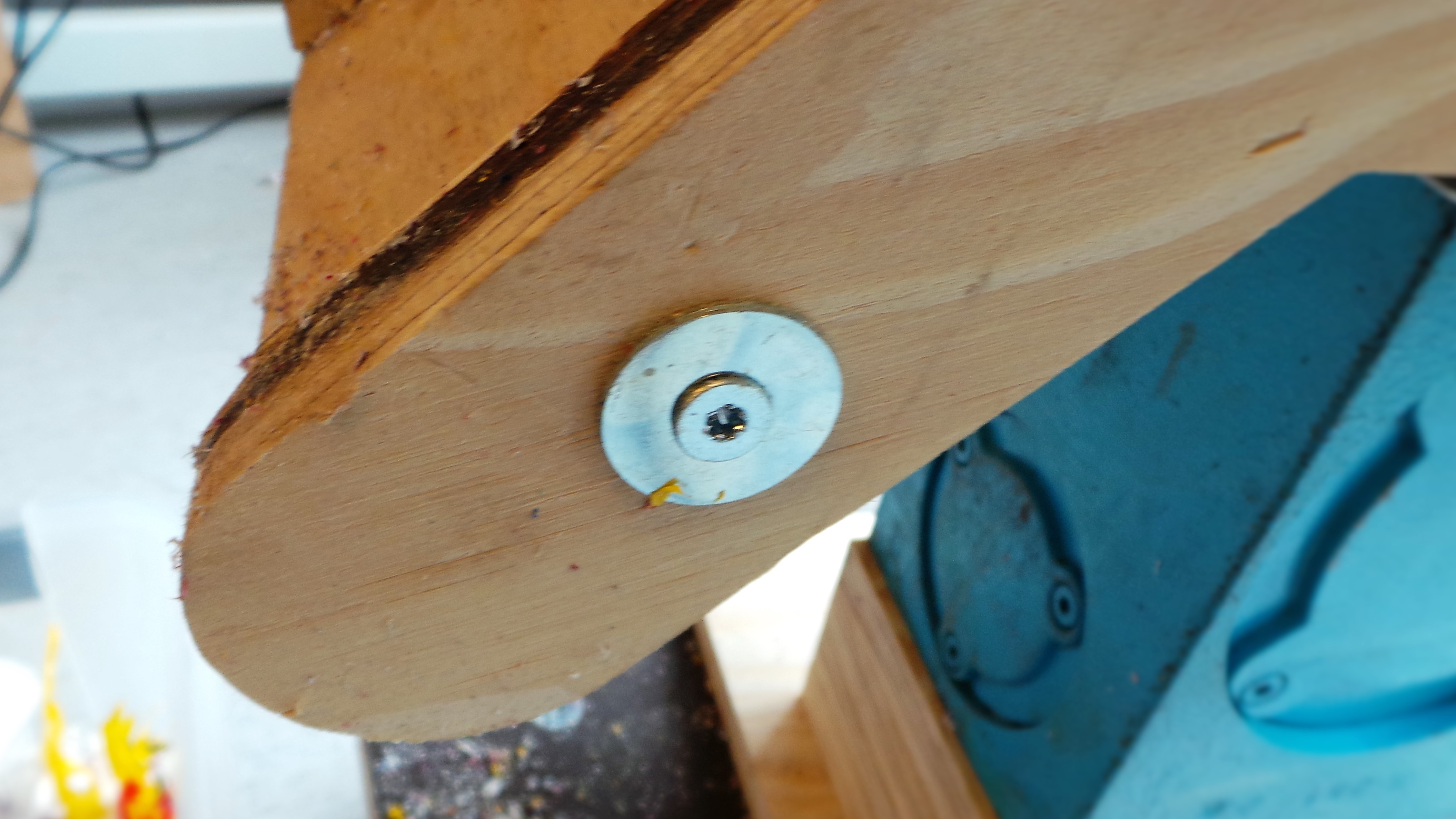
Position the motor so that the drive shaft is facing you. Drill a 3mm hole 5mm from the end of the axle. Place a nylon washer on the axle and insert a split pin in to the hole bending and trimming the legs. Slide the axle through the housing so that the washer is flush against the face the pin is flush against the washer.
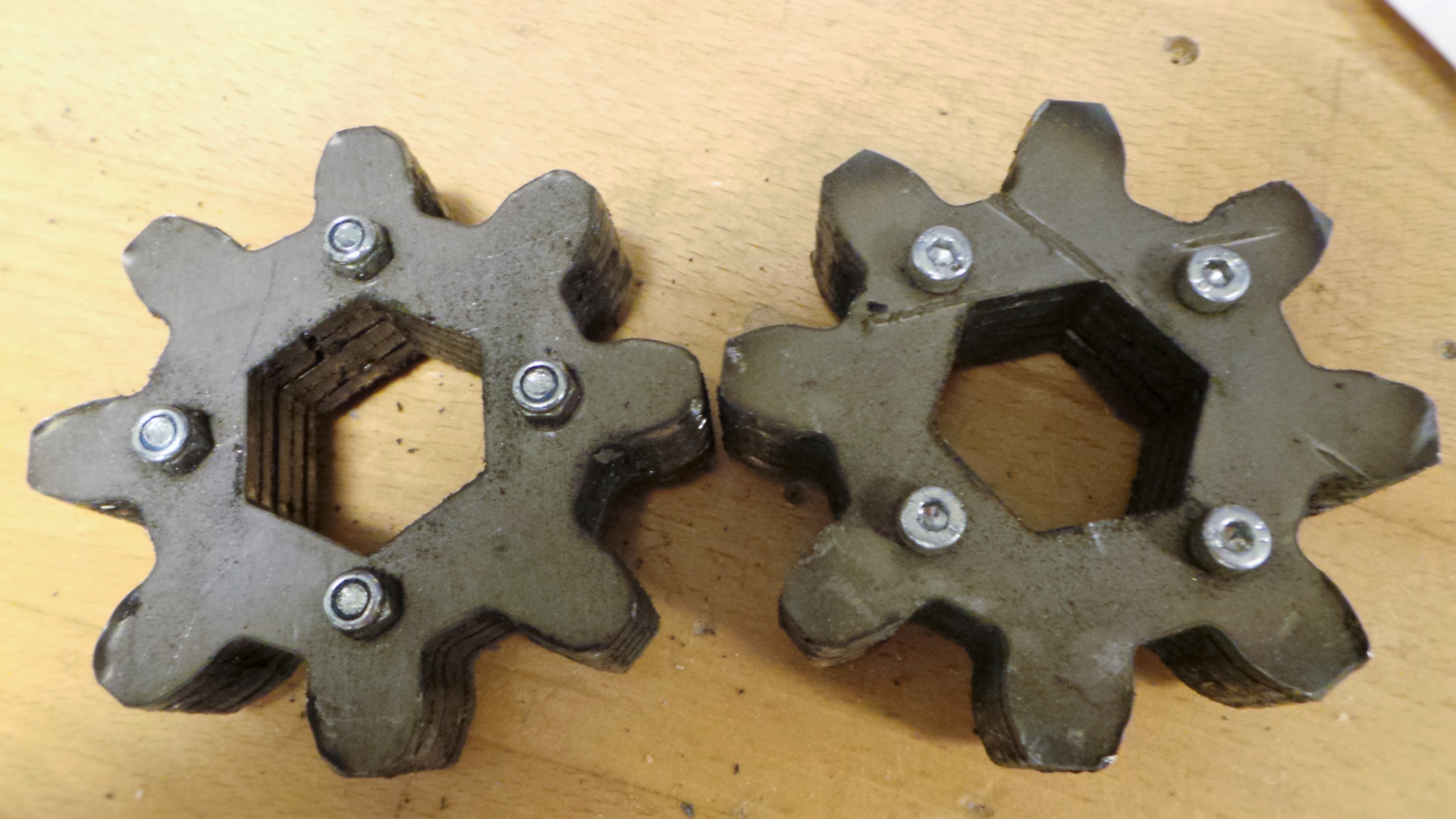
Assembling the metal gears firstly requires that all rough edges have been removed using the technique described above. Insert M4x25mm bolts through five gear plates ensuring the teeth line up properly. Tighten a nut on to each of the bolts using a torque wrench. Repeat for the second gear.
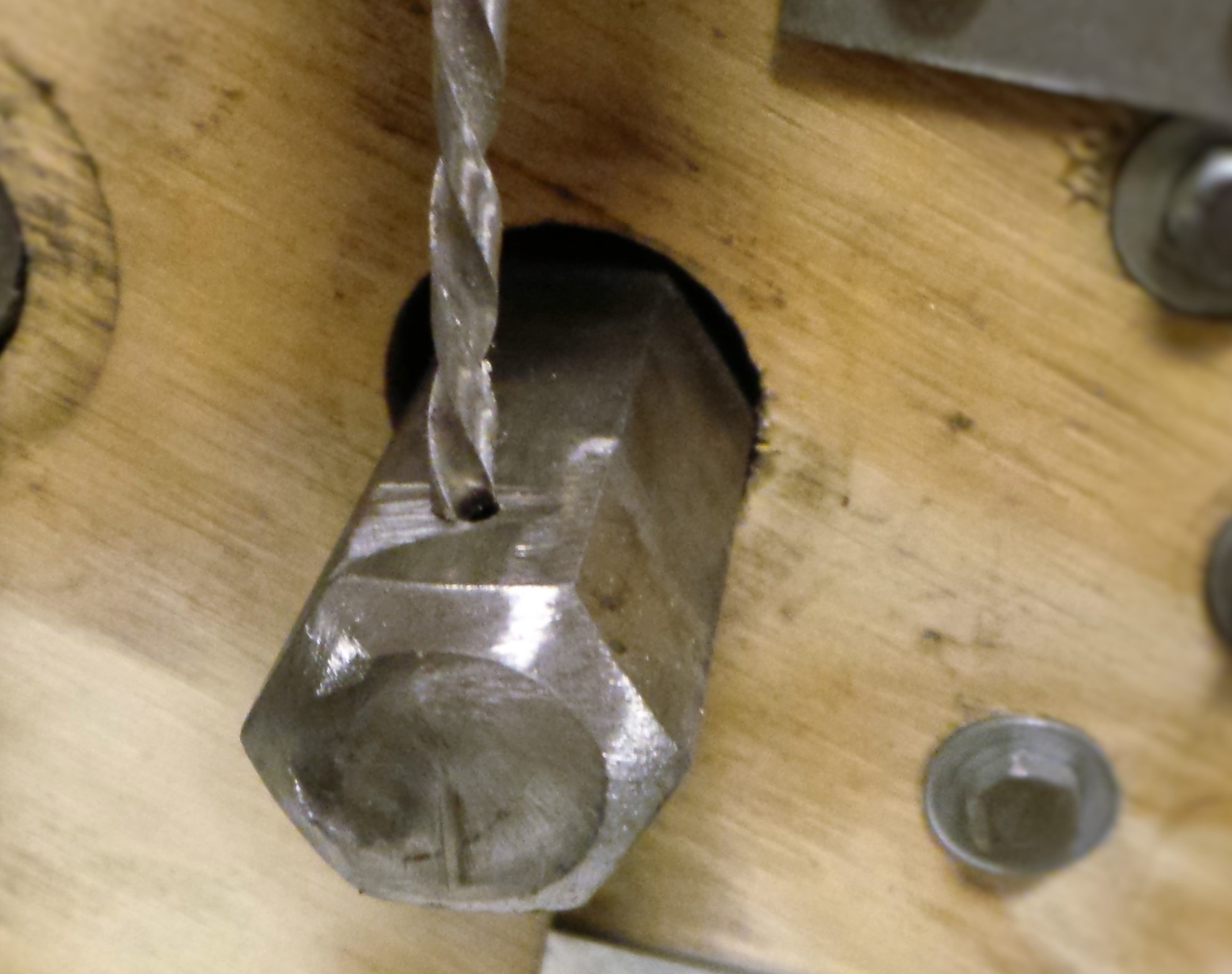
Slide the gears on to the axle the face opposite to the driveshaft with a nylon washer either side of each gear. mark the axle where the nylon washer is positioned To secure the gears in place drill a 3mm hole through the axle and insert a split pin, bending and trimming the legs.
Fasten the three layers of each wooden gear together by inserting a M4x65mm socket cap bolt through the pre-cut holes. Use a hammer if necessary. Apply glue between each layer. Tighten each nut using a torque wretch and a drill to ensure the plates are firmly held together.
Using 5x20mm screws attach one of the steel support brackets to the larger wooden gear; use a small section of hexagonal axle to ensure that it is aligned correctly. Place a nylon washer on the right hand axle, using a mallet, hammer the gear in to place with the metal bracket on the inside.
Hammer the two wooden supporting discs on to the axle. Using 4x80mm screws attach the other steel support bracket to the outside of the wooden supporting discs. Use the split pin technique described above to secure the gear on to the axle.
Attach the steel supporting bracket and the spacer to the smaller wooden gear using 5x20 ensuring that that notch lines up correctly. Hammer the gear on to the driveshaft with the steel supporting bracket facing the inside.
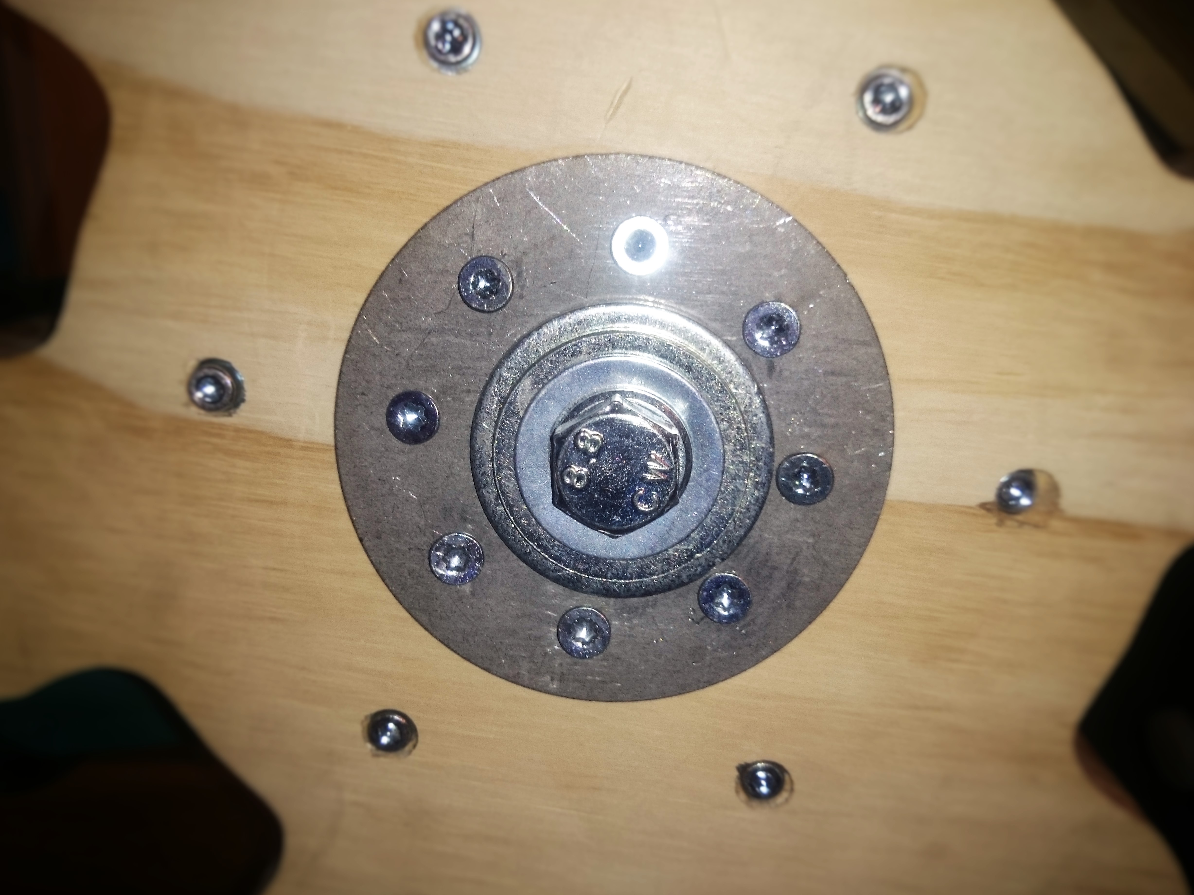
Attach the second steel supporting bracket to small wooden gear with 5x60mm screws. Using an M12, M16, Washer and M12x80mm bolt, secure the gear to the driveshaft with a torque wrench.
Part 3: Electronics
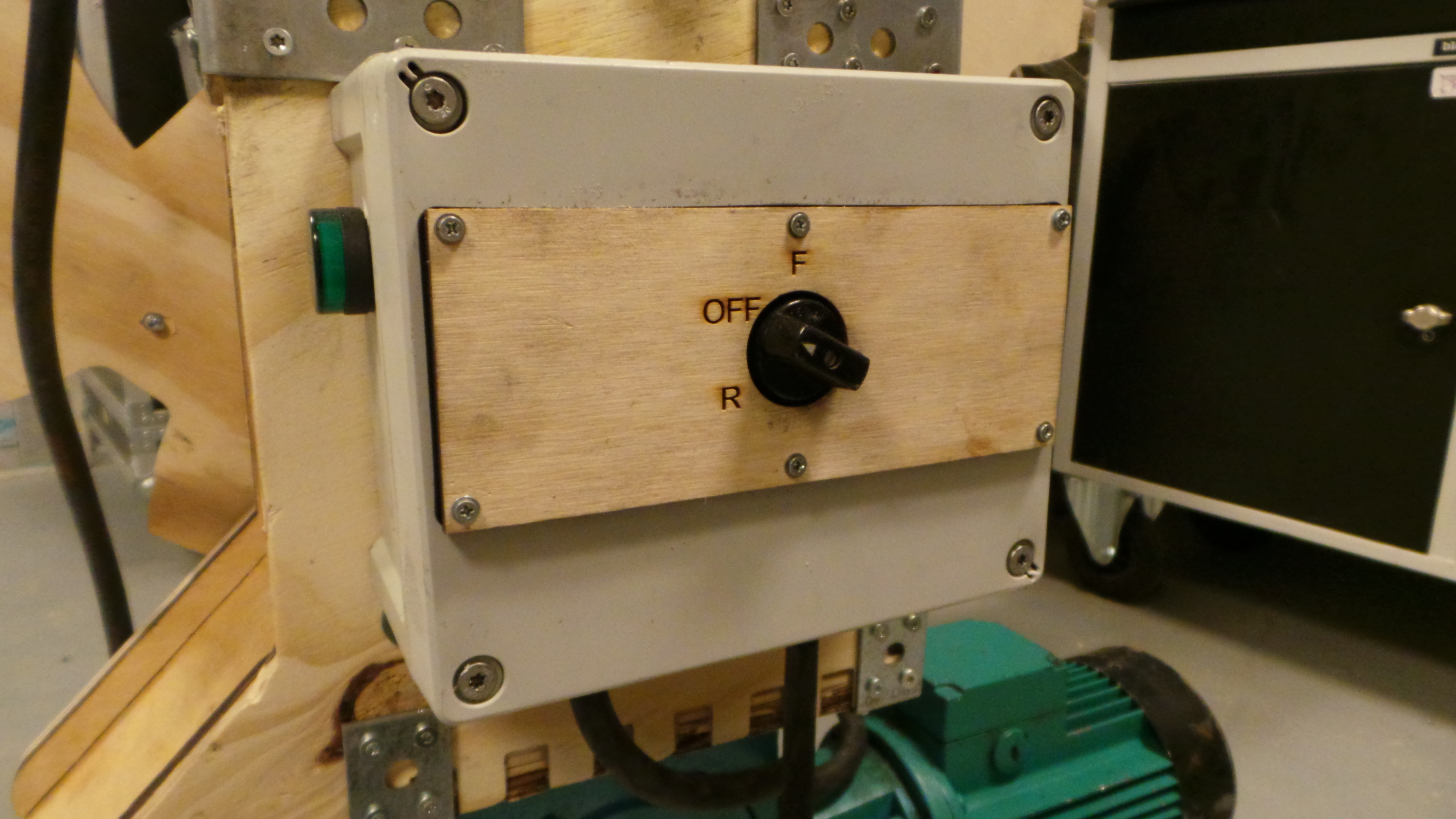
Take a 200mmx150mmx95mm plastic weather proof case and drill two 12mm holes facing holes facing downwards roughly 50mm apart in the middle of the face. Attach two M12 glands to the holes. At the top of the left face drill a 22mm Hole for the LED and secure it in place. Remove the front face, mark the canter and drill a 22mm hole for the switch. Secure the switch in place and leave the front face off.
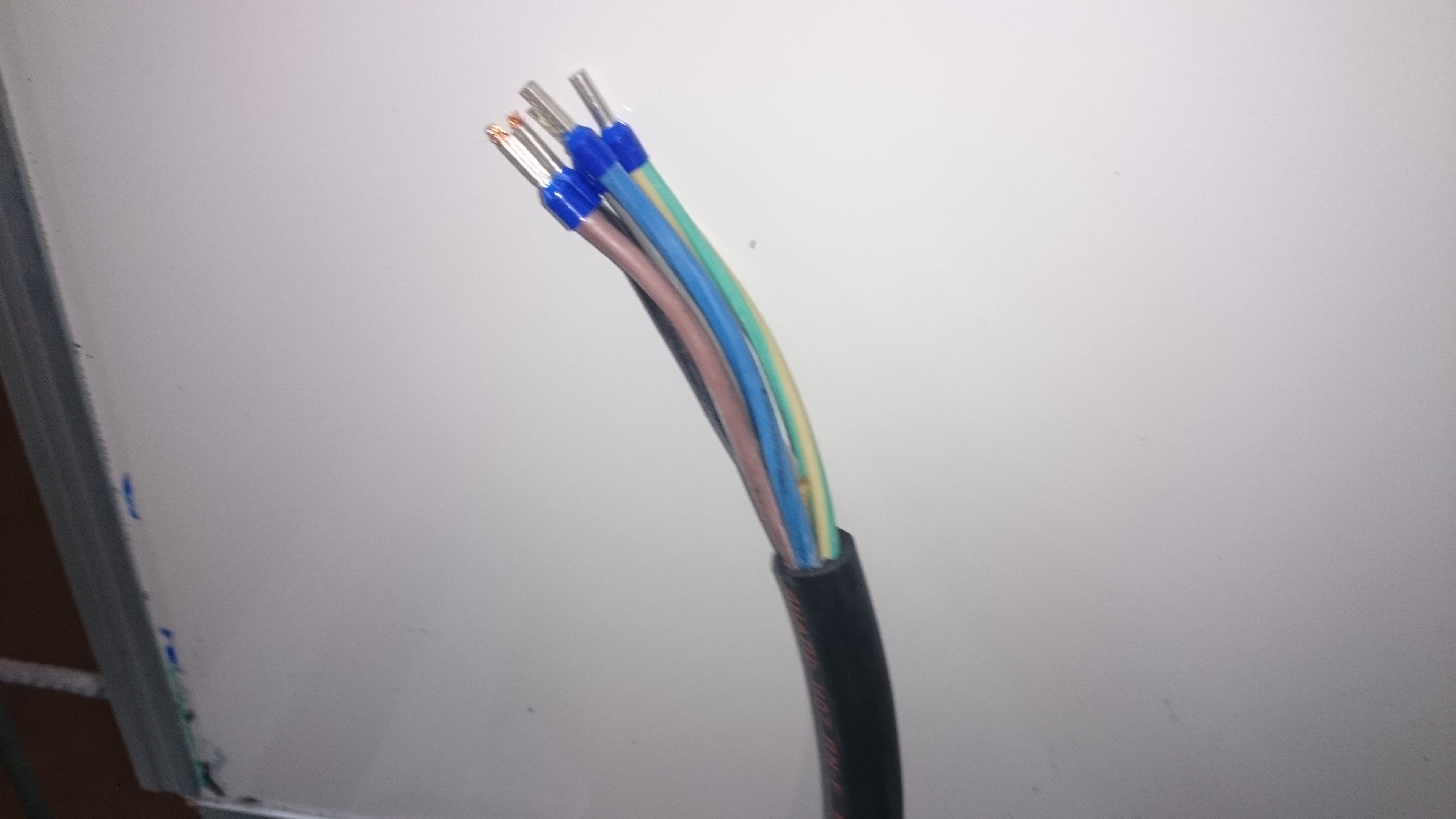
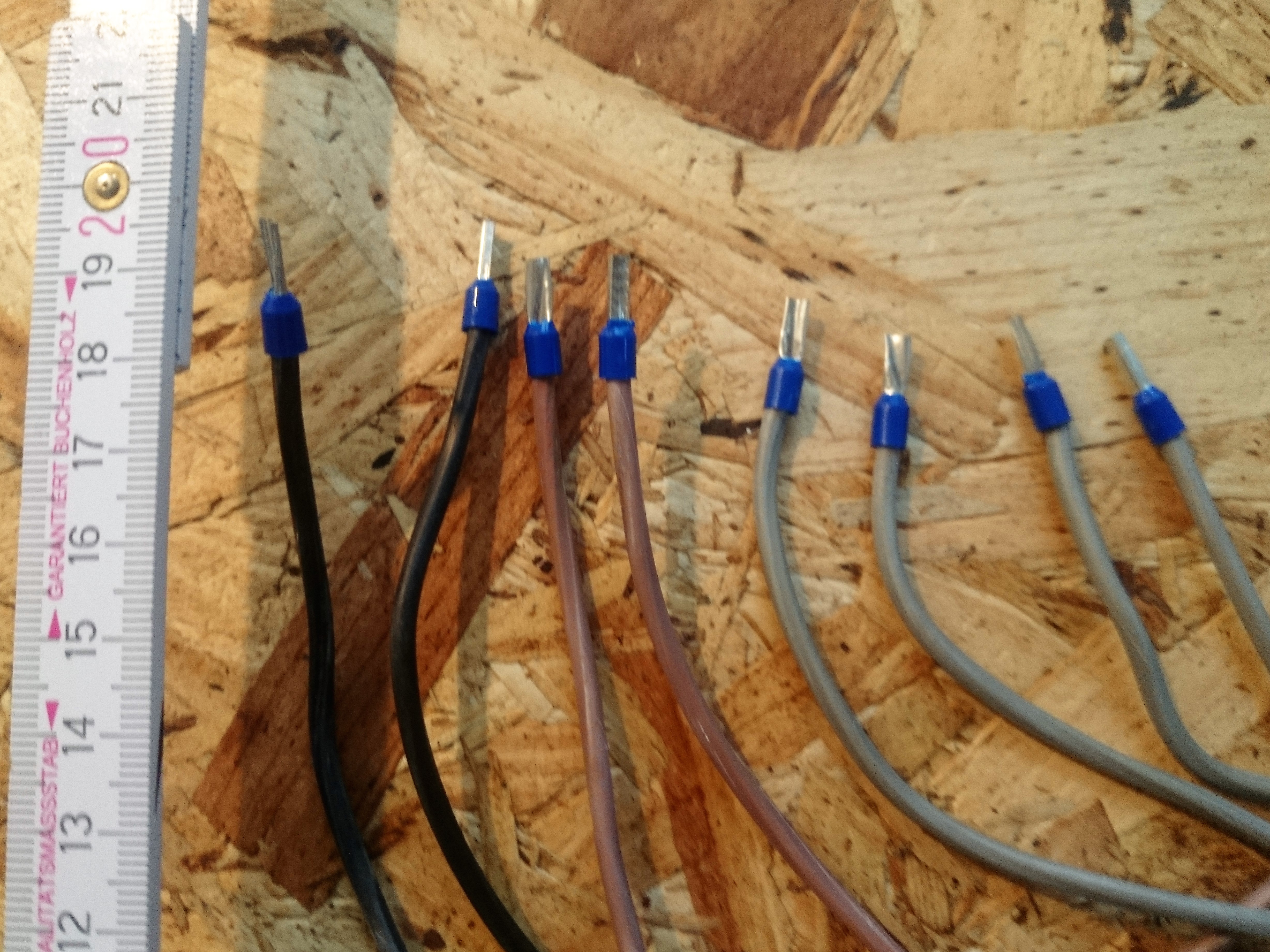
Cut a 15m and a 1m length of 12mm 5-core flexible mains cable. Carefully strip back 20mm of the outer rubber case of the ends to expose the 5 core wires. Strip back the individual wires using wire strippers. Attach crimps to the ends of each wire using a crimping tool.
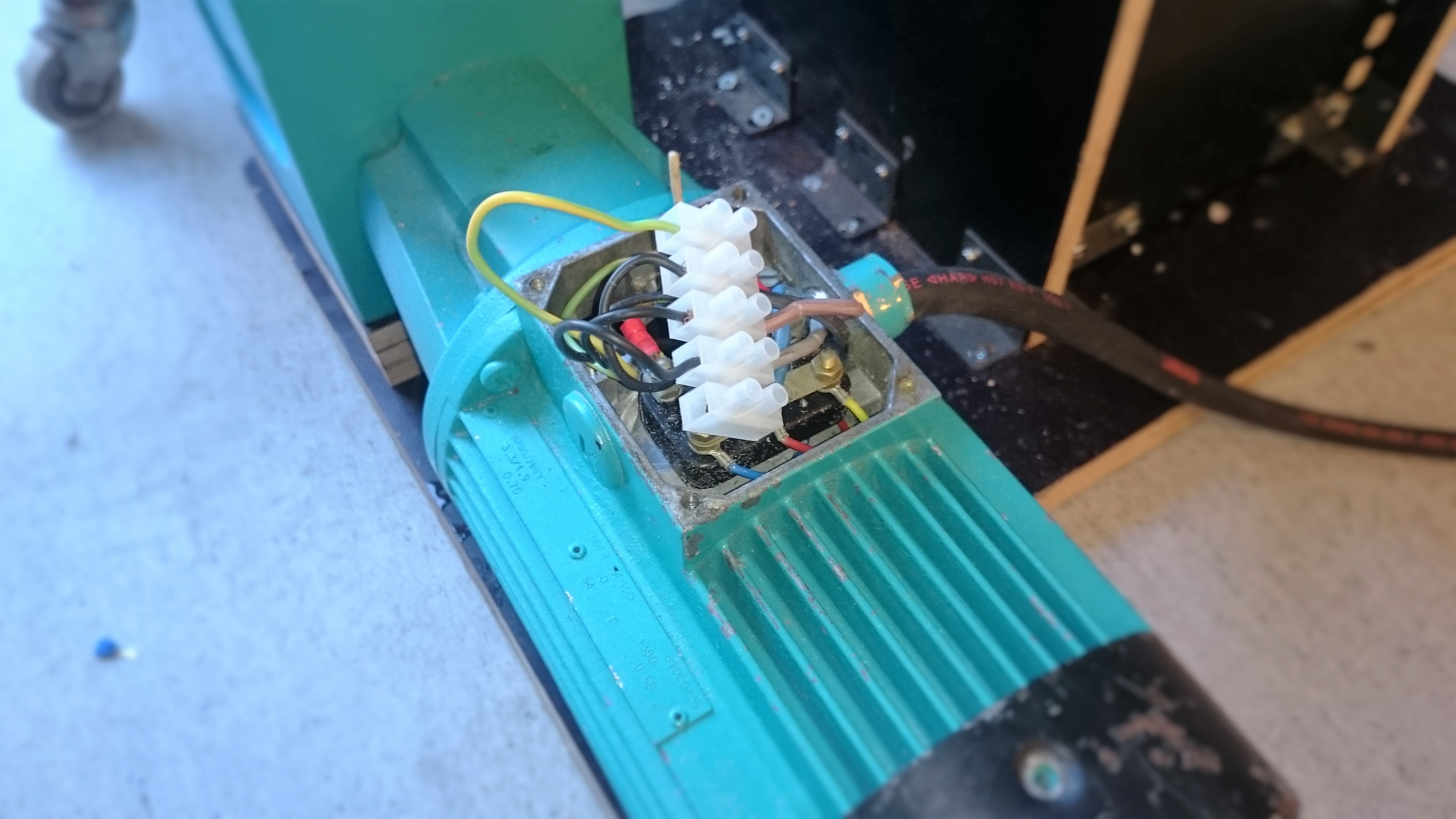
Open up the motor cover to expose the wires inside. Using two way splicing connectors attach the brown, black and red wires from the 1m cable to the three wires under the motor cover. Attach the ground wire to the outside of the case. Secure the other end of the cable the weatherpoof case using the left > gland.
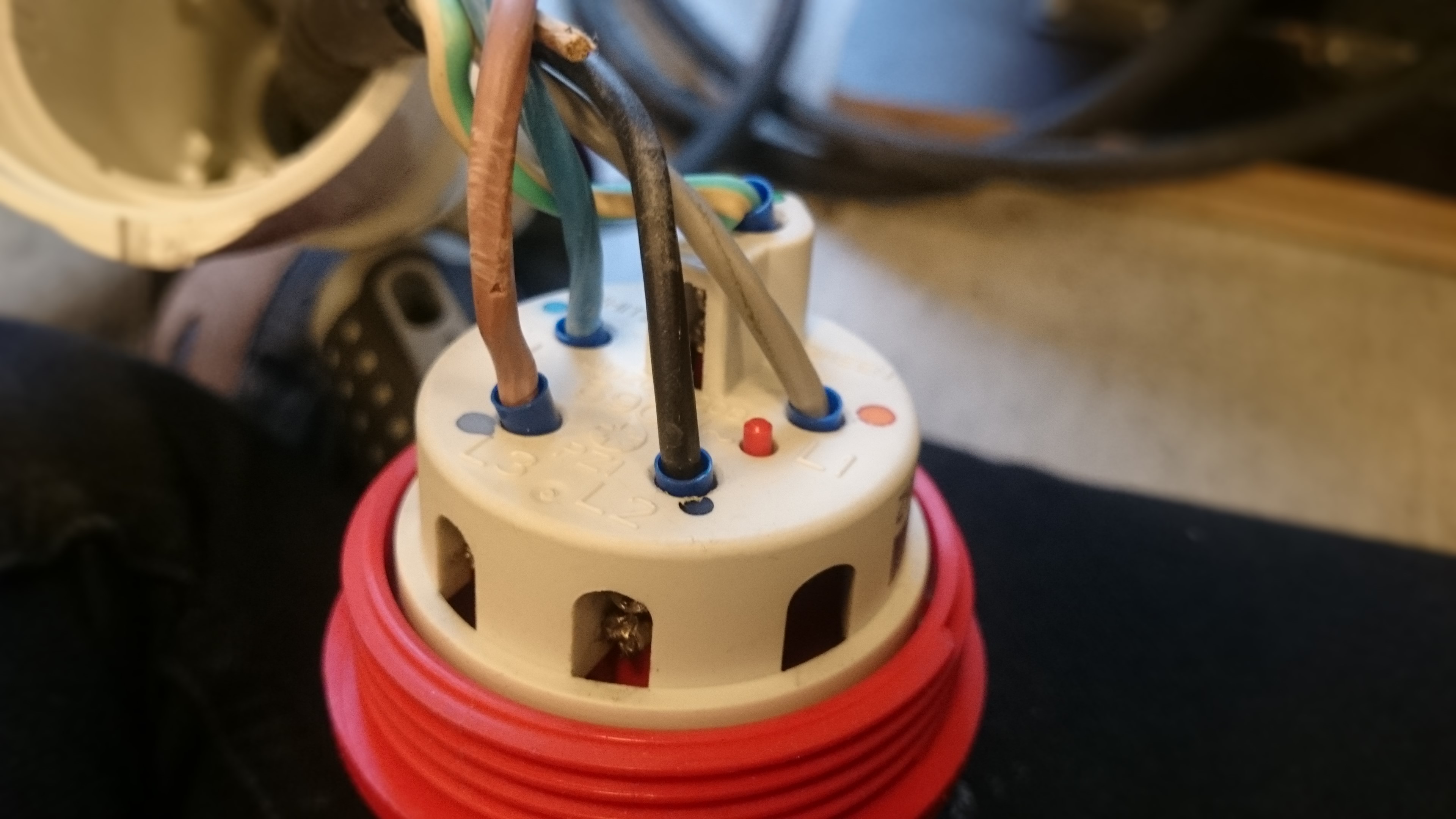
One end of the 15mm cable to a 5 pin Industrial socket is attached to the socket. To do so, unscrew the gland and separate the red and cream components using a flathead screwdriver. Insert the cable through the gland them fasten the core wires in to the five colour coded terminals using a screwdriver to tighten them in place. Re attach the red and cream sections then secure the wire in place using the gland.
Cut two 20mm lengths of brown and black wire and four 20mm lengths of grey wire. Strip and crimp the ends. Inside the weatherpoof case, attach a 3 way splicing connector to the grey wire coming from the plug socket. The Switch is split in to four rows of terminals. Use a probe to identify the row which is the constant with the other three. Attach a 20mm length of grey wire from the splicer to a pin on this row. Attach the back and brown wires from the plug socket to same row. Connect the other grey wire between the splicer and the LEDs positive terminal.
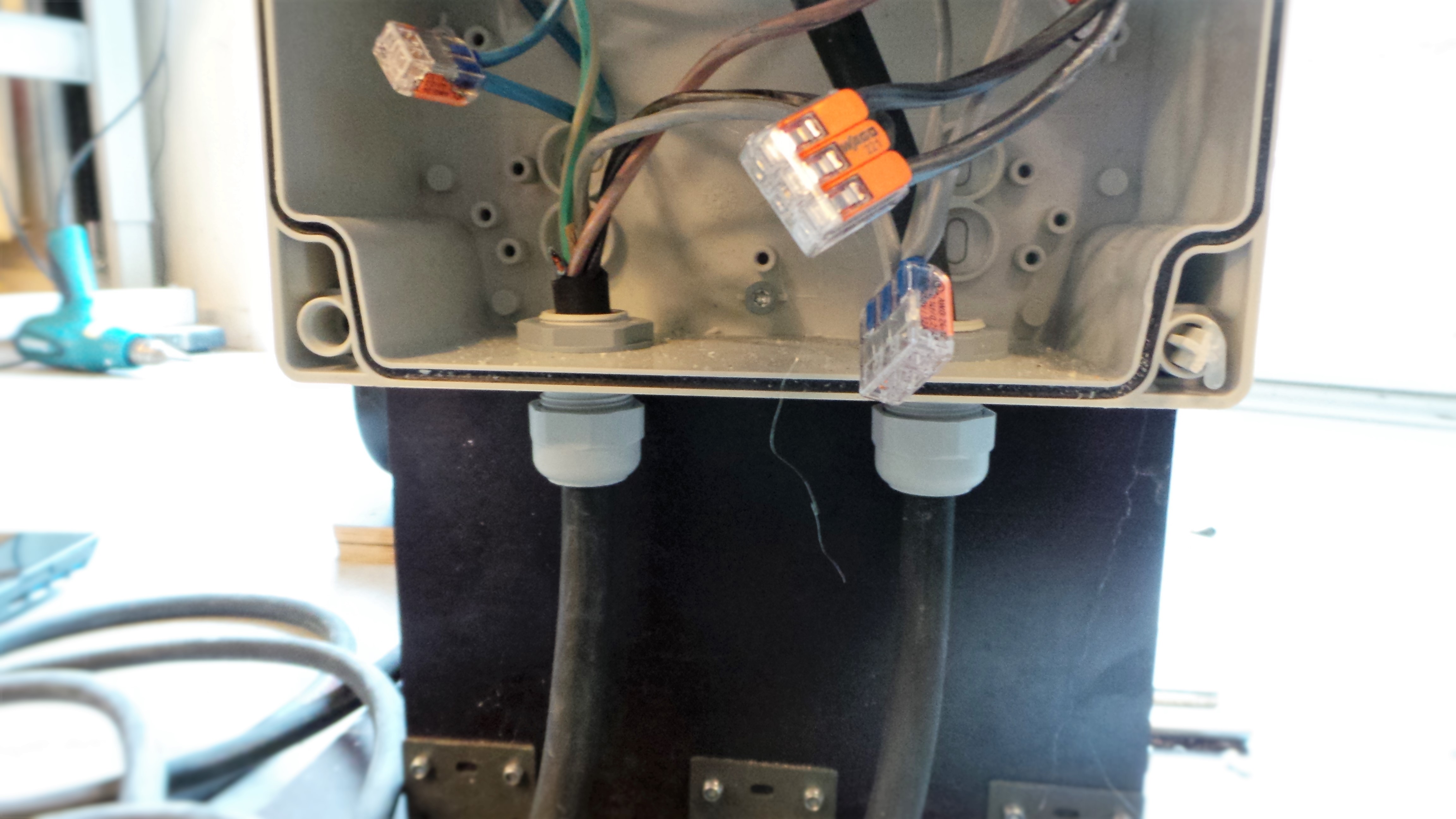
Attach a three way splicing connector to the end of each brown, black and grey wire from the motor. Attach a 20mm length of wire to the respective splicing connectors. The wires should be attached to the two extreme rows so that switch has a neutral position in the middle. For one row the wires should be attached to pin parallel to their respective colours coming from the plug socket. For the other row, two of the wires should be switched. This creates a forward and reverse function for the motor. If the directions do not seem logical to the direction the switch position then switch two of the wires under motor cover.
Attach the blue wire from the plug socket to the negative terminal of the LED. The blue wire from the motor should be cut next to the gland. Use a two way splicing connector to attach the two ground wires together.
Attach the weatherpoof case in the middle of the face opposite the drive shaft using 4.5x20mm screws. And reattach the front face. It is not a necessity but you may want to laser cut a control panel to attach to the front of the case.
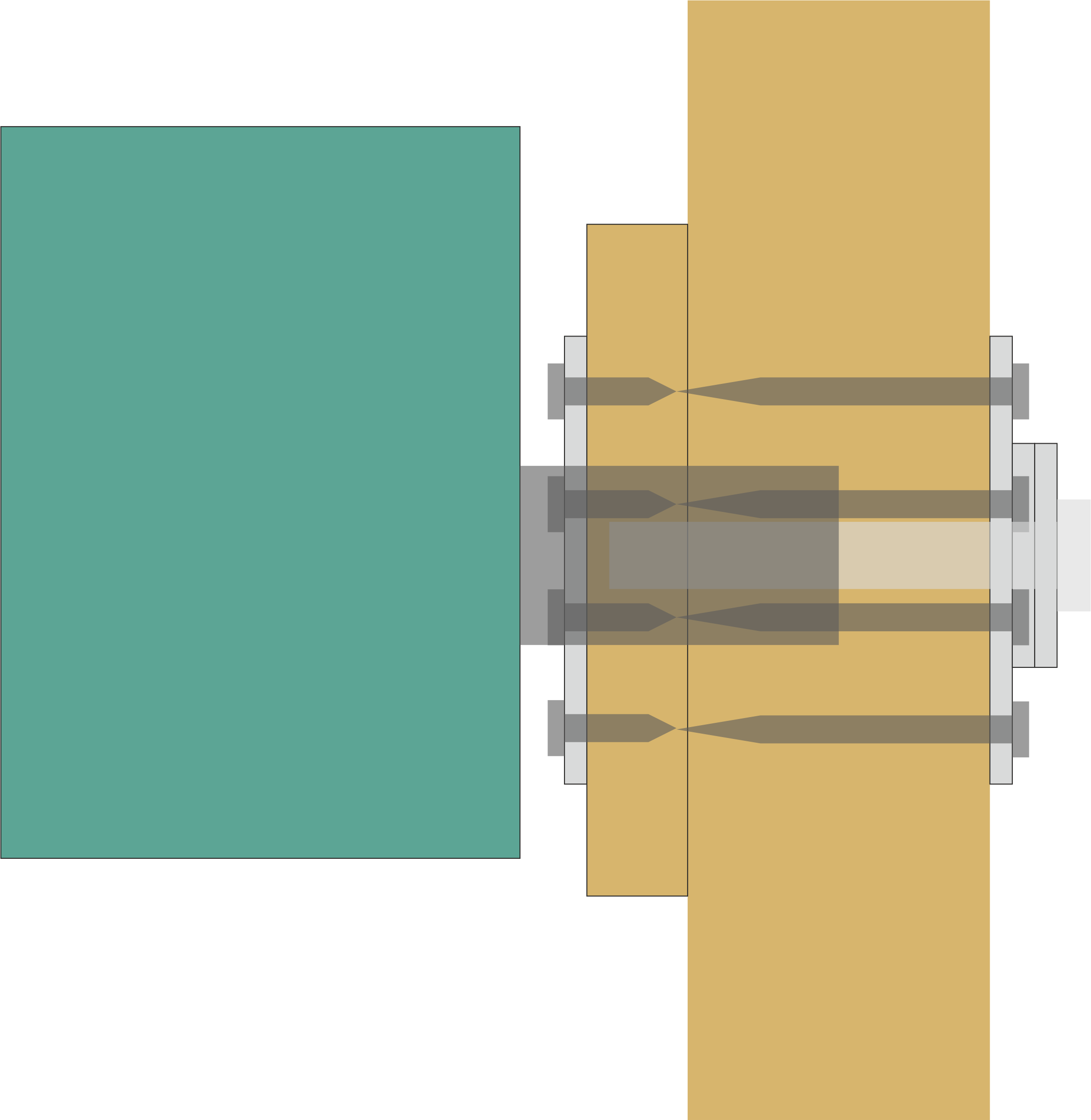
Circuit Diagram:
A “Dead Man” button may be added to the control. You will need a button or switch which needs to be pressed and held in order to be on. Attach this to the wire which is constant through the switch (e.g the one which is connected to the same pin on each three rows of the switch).
Part 4: Safety Features
The shredder is incredibly dangerous and there some strong forces involved so maximum caution and attention are advised when using the machine. To make it safer you use I have developed several safety which can be added to the shredder, It is down to your discretion which combination you chose to use based on the environment it is being used in and who by.
Drawer
The drawer is cut from 18mm Ply using a CNC machine, it also requires:
2x M6x60mm bolt
2x M6x30mm bolt
2x M6 Nuts
40x M6 Washers
2x M6x40mm Coupling Nuts
1x 156x250x3mm Ply
12x 4x20mm screws
2x 170x310 Acrylic
4x 5x50mm Screws
Firstly cut the 18mm ply using the CNC machine. For specific instructions of how to use a CNC machine Click Here.A file containing the tool path for a 3mm diameter tool can be found in the drawings folder named “Safety Draw 3mm CNC Tool Path”. Alternatively if you would like to generate your own tool path the original drawing can be found in the file named “Drawings Complete”.
Next drill four 4mm as close as possible to the four corners of the pieces of acrylic. Screw them in to the engraved section of the window frame.
Apply glue to the finger joints and assemble the body section together with the acrylic on the inside using four 4x20mm screws.
Next glue the drawer sections together and attach the handle using M6x30mm bolt, M6 Washers and the M6x40mm coupling nuts to attach the handle in place.
Attach the drawer inside the case using M6x60mm bolts and M6 washers as spacers so it runs smoothly.
Finally insert the ply in to curved groove inside of the body and screw it in place using four 4x20mm screws.
The drawer can be mounted above the blades using 5x20mm screws.
Gear Guard
A template for a gear guard has been created for the two wooden gears; it is split in to two parts, an plywood frame and an acrylic 6mm shield. The plywood frame consists of 4 18mm layers and must be CNC cut. It is recommended that you break of the frame in to smaller sections before drawing the tool path to minimise material usage. Next cut the acrylic panels using a laser cutter. The guard is held together using M4x70mm Socket cap bolts and secured to the base of the shredder using 8 M5x60 Screws.
Underside Guard
An addition square of acrylic may be attached above the ramp of the shredder to prevent objects touching the blade from the underside.
Metal Gear Guard
A cutting template for box to cover the metal gears from 5-6mm acrylic can be can be found in the drawing folder.

Plastic Shredder by Jason Knight is licensed under a Creative Commons Attribution-NonCommercial-ShareAlike 4.0 International License.