Maker kit tutorial
This is an in progress tutorial
The IO kit is a collection of components that enables you to make a wide array of experiments. The kit is made for interactive design module 2 for Humtek.
Box design

Download templates here.
Components
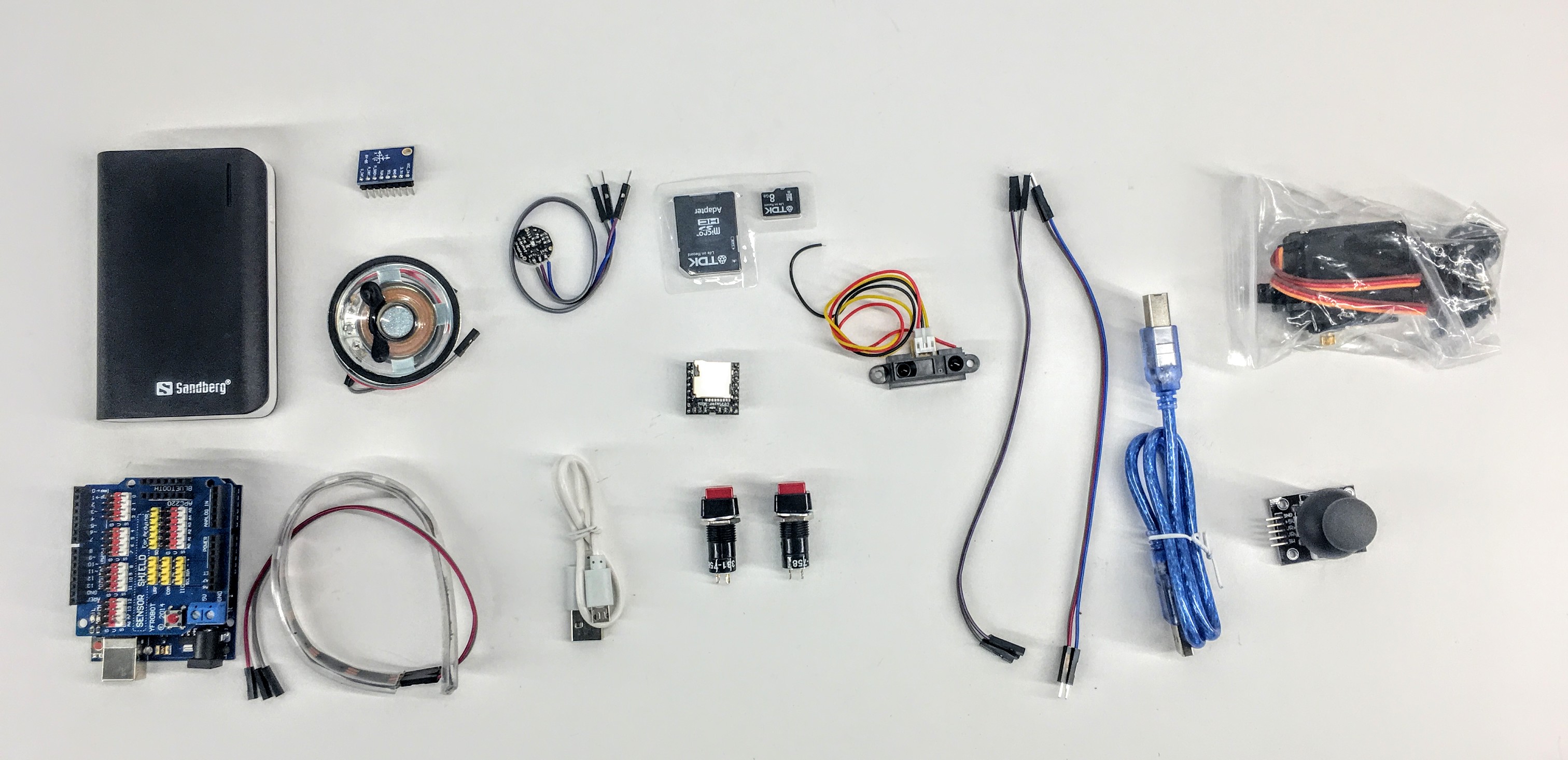
- Powerbank
- Micro usb cable for power bank
- 2xButtons
- SDCard
- Micro SD card converter
- USB Cable
- Arduino With Shield
- Joystick
- Neopixel string
- Infrared Distance sensor.
- MP3 Player
- IMU
- Servo motor

Exercises/examples:
Download arduino. See general guides on programming here and here.
Create a touch sensor
The simplest and most interesting input is a touch sensor. Do the following:
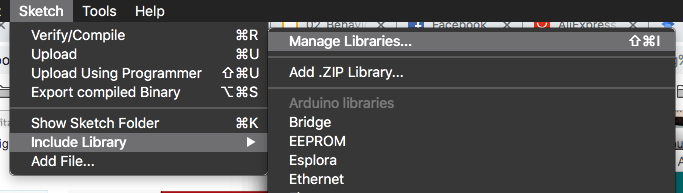
Go to manage libraries:
Install ADCTouch by Alexander Pruss

Put one wire in analog zero.

Use the following code:
    #include <ADCTouchSensor.h>
    ADCTouchSensor touch0 = ADCTouchSensor(A0, -1);

    void setup()
    {
        Serial.begin(9600);

        touch0.begin();

    }

    void loop()
    {
        float value0 = touch0.read();
        Serial.println(value0);    //send (boolean) pressed or not pressed

    }
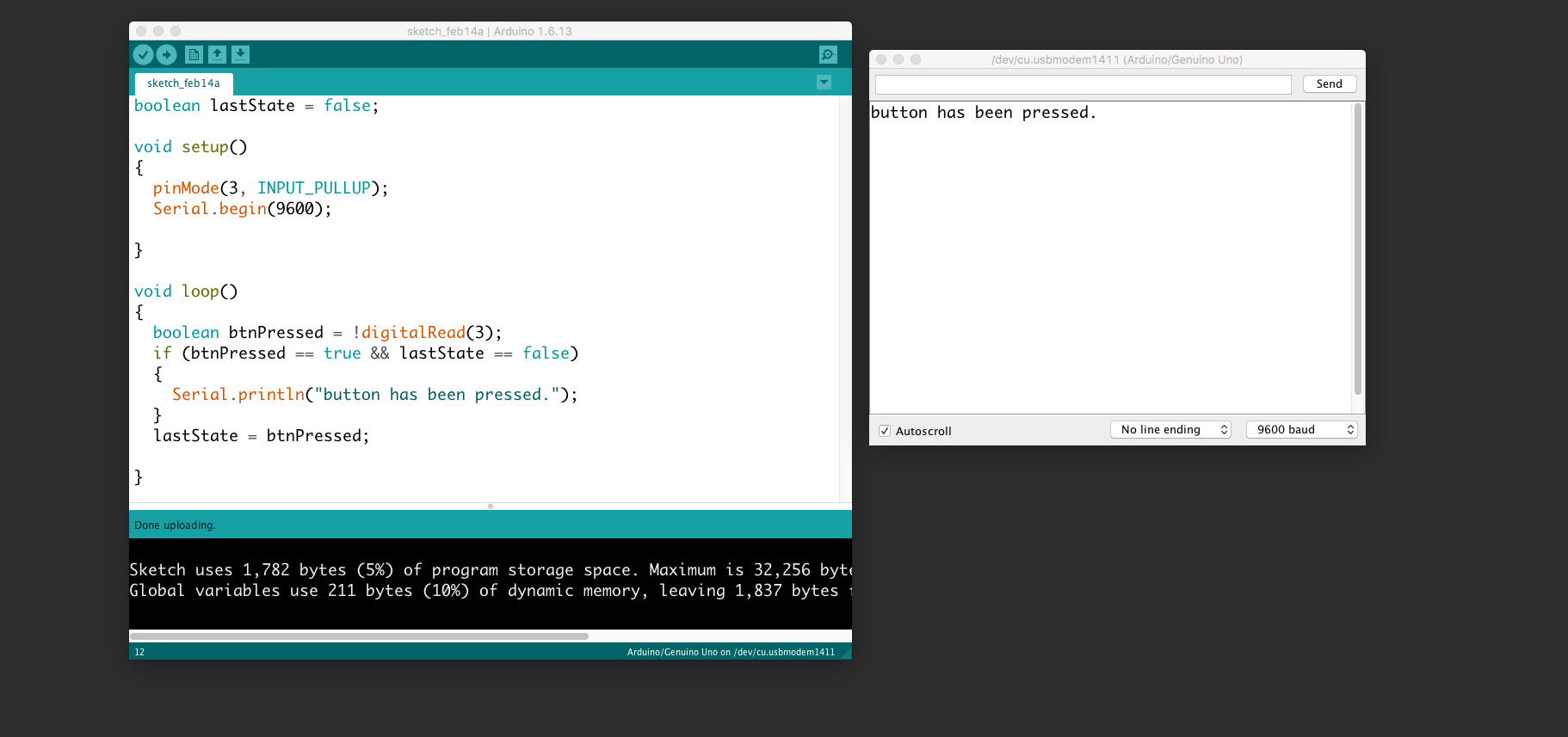
Go to the serial monitor to see the output (top left corner):

Detecting button pressed STATE
 In the following example, we connect a button to the Arduino and send a message repeatiatly somebody presses it. Be aware that we use the internal pull-up so the button has to be connected to the ground. Further, we use the serial communication to receive the messages to our prompt. Use the "search icon" (upper right corner) to view the serial prompt.

        void setup()
        {
            pinMode(3, INPUT_PULLUP);
            Serial.begin(9600);

        }

        void loop()
        {
            boolean btnPressed = !digitalRead(3);
            if(btnPressed == true)
            {
                Serial.println("button has been pressed.");
            }

        }
Detecting button single press - An EVENT
The event of pressing the button. Use the same wiring as above.
  boolean lastState = false;

  void setup()
  {
    pinMode(3, INPUT_PULLUP);
    Serial.begin(9600);

  }

  void loop()
  {
    boolean btnPressed = !digitalRead(3);
    if (btnPressed == true && lastState == false)
    {
      Serial.println("button has been pressed.");
    }
    lastState = btnPressed;

  }
Control neopixels
Neopixels are versatile light strings where each diode can be controlled individually. Each one has Red, Green, and Blue and can be from 0 to 255 in brightness. Multiple libraries exists to use noepixels. We suggest you use fastled.
Add the library: "menu->sketch->include library->manage libraries"

Search for "fastled" and click install

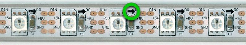
Use this wiring:

IMPORTANT: connect 5v to v, Di to s and G to g AND make sure the direction is correct:
This example sketch will turn red, green and blue for the first three pixels:
  #include "FastLED.h"

  // How many leds in your strip?
  #define NUM_LEDS 10
  #define DATA_PIN 4


  // Define the array of leds
  CRGB leds[NUM_LEDS];

  void setup() {
          FastLED.addLeds<NEOPIXEL, DATA_PIN>(leds, NUM_LEDS);
  }

  void loop() {
    // Turn the LED on, then pause
    leds[0]= CRGB( 255, 0, 0);
    leds[1]= CRGB( 0, 255, 0);
    leds[2]= CRGB( 0, 0, 255);
    FastLED.show();

  }
This example will turn all the 12 leds red:
#include "FastLED.h"

// How many leds in your strip?
#define NUM_LEDS 13
#define DATA_PIN 4


// Define the array of leds
CRGB leds[NUM_LEDS];

void setup() {
  FastLED.addLeds<NEOPIXEL, DATA_PIN>(leds, NUM_LEDS);
}

void loop() {

  for (int i = 0; i < NUM_LEDS; i = i + 1)
  {
    leds[i] = CRGB( 255, 0, 0);
  }
  FastLED.show();

}
This example makes a chase
#include "FastLED.h"

// How many leds in your strip?
#define NUM_LEDS 13
#define DATA_PIN 4


// Define the array of leds
CRGB leds[NUM_LEDS];

void setup() {
  FastLED.addLeds<NEOPIXEL, DATA_PIN>(leds, NUM_LEDS);
  Serial.begin(9600);
}
int numLedsOn = 0;
void loop() {

  for (int i = 0; i < NUM_LEDS; i = i + 1)
  {
    if (i < numLedsOn)
    {
      leds[i] = CRGB( 255, 0, 0);
    }
    else
    {
      leds[i] = CRGB( 0, 0, 0);
    }
  }

  FastLED.show();
  numLedsOn = numLedsOn + 1;
  if (numLedsOn == NUM_LEDS)
  {
    numLedsOn = 0;
  }
  Serial.println(numLedsOn);

  delay(100);

}
Button + neopixels
This example connects the button (input) to the neopixels (output). Thus, your first interactive installation.

  #include "FastLED.h"

  // How many leds in your strip?
  #define NUM_LEDS 10
  #define DATA_PIN 4


  // Define the array of leds
  CRGB leds[NUM_LEDS];

  void setup() {
    FastLED.addLeds<NEOPIXEL, DATA_PIN>(leds, NUM_LEDS);
    pinMode(3, INPUT_PULLUP);
  }

  void loop() {

    boolean btnPressed = !digitalRead(3);
    if (btnPressed == true)
    {
      leds[0] = CRGB( 255, 0, 0);
      leds[1] = CRGB( 0, 255, 0);
      leds[2] = CRGB( 0, 0, 255);
    }
    else
    {
      leds[0] = CRGB( 0, 0, 0);
      leds[1] = CRGB( 0, 0, 0);
      leds[2] = CRGB( 0, 0, 0);

    }
    FastLED.show();

  }
Control a servo
Servos are motors in which their position can be controlled. They have an action radius of 0 to 180 degrees. Some servos are "hacked" to be continuous. They will rotate 360 degrees, but cannot be positioned. They are then able to move in a controlled speed and direction. Orange wire is signal and should be connected to S.

  #include <Servo.h>

  Servo myservo;  // create servo object to control a servo
  // twelve servo objects can be created on most boards

  int pos = 0;    // variable to store the servo position

  void setup() {
    myservo.attach(5);  // attaches the servo on pin 5 to the servo object
  }

  void loop() {

    for (pos = 0; pos <= 180; pos += 1) { // goes from 0 degrees to 180 degrees
      // in steps of 1 degree
      myservo.write(pos);              // tell servo to go to position in variable 'pos'
      delay(15);                       // waits 15ms for the servo to reach the position
    }
    for (pos = 180; pos >= 0; pos -= 1) { // goes from 180 degrees to 0 degrees
      myservo.write(pos);              // tell servo to go to position in variable 'pos'
      delay(15);                       // waits 15ms for the servo to reach the position
    }
  }
Joystick

  void setup() {
    Serial.begin(9600);
  }

  void loop() {
    Serial.println(analogRead(0));
  }
Joystick + servo

    #include <Servo.h>

    Servo myservo;

    void setup() {
      myservo.attach(5);  // attaches the servo on pin 5 to the servo object
    }

    void loop() {
      myservo.write(map(analogRead(0), 0, 1024, 0, 180));

    }
Distance sensor

One simple sensor to use is the distance sensor. This is an infrared sensor which receives values from 0-1024 relative to about 15cm to 60cm.
  void setup() {
    Serial.begin(9600);
  }

  void loop() {
    Serial.println(analogRead(A0)); // pin Analog 0
  }
Timing without delay
Using delay is bad practice because it halts everything on the board. Instead use "millis()". This example does something every two seconds:
unsigned long timer = 0;
void setup()
{

}

void loop()
{
    if(millis()-timer > 2000) // do something every two seconds)
    {
      timer = millis();
       //do something here
    }
}
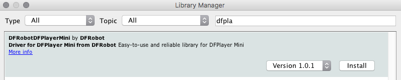
MP3 Player
Use the MP3 player to make interactive sounds for voice commands and games.
!!! IMPORTANT - USE VERSION 1.01 for the code example below.

Remember to install the library like above with neopixels:
Simple sample code:
    #include <SoftwareSerial.h>
    #include "Arduino.h"
    #include <DFRobotDFPlayerMini.h>

    SoftwareSerial mySoftwareSerial(10, 11); // RX, TX - mp3
    DFRobotDFPlayerMini myDFPlayer;
    boolean lastState = false;

    void printDetail(uint8_t type, int value);
    void setup() {
      mySoftwareSerial.begin(9600); //for mp3 player
      Serial.begin(9600);

     while(!myDFPlayer.begin(mySoftwareSerial)) { //Use softwareSerial to communicate with mp3.
        Serial.println(".");
      delay(300);

      }
      myDFPlayer.volume(20); //Set volume value. From 0 to 30

      pinMode(3, INPUT_PULLUP);
        myDFPlayer.play(1); //Play the first mp3
    }

    void loop() {

    }
Accelerometer
Use the accelerometer to detect movement.


Download all the libraries here. They need to be placed in your "documents/arduino/libraries" folder.
  // Arduino code and libraries are available to download - link below the video.

  // Output for viewing with Serial Oscilloscope: accX,accY,magZ // gyrX, gyrY and gyrZ are commented out

  /*
    Arduino     MARG GY-85
    A5            SCL
    A4            SDA
    3.3V          VCC
    GND           GND
  */

  #include <Wire.h>
  #include <ADXL345.h>  // ADXL345 Accelerometer Library
  #include <HMC5883L.h> // HMC5883L Magnetometer Library
  #include <ITG3200.h>

  ADXL345 acc; //variable adxl is an instance of the ADXL345 library
  HMC5883L compass;
  ITG3200 gyro = ITG3200();
  float  gx, gy, gz;
  float  gx_rate, gy_rate, gz_rate;
  int ix, iy, iz;
  float anglegx = 0.0, anglegy = 0.0, anglegz = 0.0;
  int ax, ay, az;
  int rawX, rawY, rawZ;
  float X, Y, Z;
  float rollrad, pitchrad;
  float rolldeg, pitchdeg;
  int error = 0;
  float aoffsetX, aoffsetY, aoffsetZ;
  float goffsetX, goffsetY, goffsetZ;
  unsigned long time, looptime;

  void setup() {
    Serial.begin(9600);
    acc.powerOn();
    compass = HMC5883L();
    error = compass.SetScale(1.3); // Set the scale to +/- 1.3 Ga of the compass
    if (error != 0) // If there is an error, print it out.
      Serial.println(compass.GetErrorText(error));

    // Serial.println("Setting measurement mode to continous");
    error = compass.SetMeasurementMode(Measurement_Continuous); // Set the measurement mode to Continuous
    if (error != 0) // If there is an error, print it out.
      Serial.println(compass.GetErrorText(error));
    for (int i = 0; i <= 200; i++) {
      acc.readAccel(&ax, &ay, &az);
      if (i == 0) {
        aoffsetX = ax;
        aoffsetY = ay;
        aoffsetZ = az;
      }
      if (i > 1) {
        aoffsetX = (ax + aoffsetX) / 2;
        aoffsetY = (ay + aoffsetY) / 2;
        aoffsetZ = (az + aoffsetZ) / 2;
      }
    }
    for (int i = 0; i <= 200; i++) {
      gyro.readGyro(&gx, &gy, &gz);
      if (i == 0) {
        goffsetX = gx;
        goffsetY = gy;
        goffsetZ = gz;
      }
      if (i > 1) {
        goffsetX = (gx + goffsetX) / 2;
        goffsetY = (gy + goffsetY) / 2;
        goffsetZ = (gz + goffsetZ) / 2;
      }
    }


    delay(1000);
    gyro.init(ITG3200_ADDR_AD0_LOW);
    // Serial.print("zero Calibrating...");
    // gyro.zeroCalibrate(2500, 2);
    // Serial.println("done.");
  }

  void loop() {

    updateData();
    // Accelerometer, Magnetometer and Gyroscope Output
    Serial.print(rolldeg);
    Serial.print(",");
    Serial.print(pitchdeg);  // calculated angle in degrees
    // Serial.print(",");
    // Serial.print(headingDegrees);

    //Serial.print(anglegx);
    // Serial.print(",");
    //Serial.print(anglegy);
    //Serial.print(",");
    //Serial.println(anglegz);
    //Serial.println(looptime);
    //Output(raw, scaled, heading, headingDegrees);
  }


  void updateData()
  {

    // code fragment for Accelerometer angles (roll and pitch)
    time = millis();
    acc.readAccel(&ax, &ay, &az); //read the accelerometer values and store them in variables  x,y,z
    rawX = ax - aoffsetX;
    rawY = ay - aoffsetY;
    rawZ = az  - (255 - aoffsetZ);
    X = rawX / 256.00; // used for angle calculations
    Y = rawY / 256.00; // used for angle calculations
    Z = rawZ / 256.00; // used for angle calculations
    rollrad = atan(Y / sqrt(X * X + Z * Z)); // calculated angle in radians
    pitchrad = atan(X / sqrt(Y * Y + Z * Z)); // calculated angle in radians
    rolldeg = 180 * (atan(Y / sqrt(X * X + Z * Z))) / PI; // calculated angle in degrees
    pitchdeg = 180 * (atan(X / sqrt(Y * Y + Z * Z))) / PI; // calculated angle in degrees

    // Code fragment for Magnetometer heading (yaw)
    MagnetometerRaw raw = compass.ReadRawAxis();
    MagnetometerScaled scaled = compass.ReadScaledAxis();
    int MilliGauss_OnThe_XAxis = scaled.XAxis;// (or YAxis, or ZAxis)
    float heading = atan2(scaled.YAxis, scaled.XAxis);
    float declinationAngle = 0.0457;
    heading += declinationAngle;
    if (heading < 0)
      heading += 2 * PI;
    if (heading > 2 * PI)
      heading -= 2 * PI;
    float headingDegrees = heading * 180 / M_PI;

    // Code fragment for Gyroscope (roll, pitch, yaw)
    gyro.readGyro(&gx, &gy, &gz);
    looptime = millis() - time;
    gx_rate = (gx - goffsetX) / 14.375;
    gy_rate = (gy - goffsetY) / 14.375;
    gz_rate = (gz - goffsetZ) / 14.375;
    delay(100);
    /* Serial.print(gx_rate);  // calculated angle in degrees
      Serial.print(",");
      Serial.print(gy_rate);
      Serial.print(",");
      Serial.print(gz_rate);
      Serial.println(",");
    */
    anglegx = anglegx + (gx_rate * looptime);
    anglegy = anglegy + (gx_rate * looptime);
    anglegz = anglegz + (gz_rate * looptime);

  }

  void Output(MagnetometerRaw raw, MagnetometerScaled scaled, float heading, float headingDegrees)
  {
    Serial.print("Raw:\t");
    Serial.print(raw.XAxis);
    Serial.print("   ");
    Serial.print(raw.YAxis);
    Serial.print("   ");
    Serial.print(raw.ZAxis);
    Serial.print("   \tScaled:\t");
    Serial.print(scaled.XAxis);
    Serial.print("   ");
    Serial.print(scaled.YAxis);
    Serial.print("   ");
    Serial.print(scaled.ZAxis);
    Serial.print("   \tHeading:\t");
    Serial.print(heading);
    Serial.print(" Radians   \t");
  }
Or use this code:
https://docs.google.com/uc?authuser=0&id=0BygvzTqnzm_wUUpZR1U3UDA5akE&export=download
Based on this instructables
Microphone: Get the volume
You can use the little volume circuit to get the volume. I recommend you use the serial plotter in the arduino gui to see the reactions. Turn the little screw on the blue component to change the sensitivity. It should be around 500 when no sound is present.
int soundPin = A0;
float sensorValue = 0;
float volume = 0;
    void setup ()
    {
      Serial.begin (9600);
    }

    void loop ()
    {
      sensorValue = analogRead (soundPin);
      volume = ((float)abs(sensorValue - 670)) * 0.1f + volume * 0.9f;
      Serial.print (sensorValue);
      Serial.print(",");
      Serial.println(volume * 100);

      //delay (2);
    }