Make your own spirograph
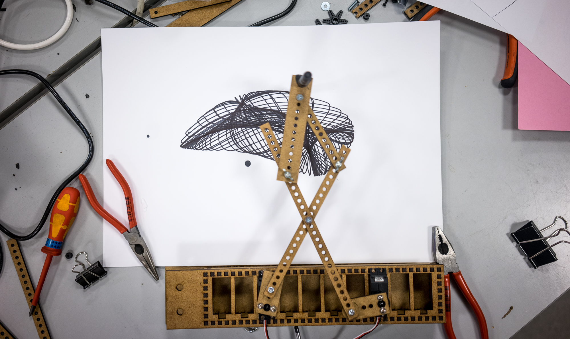
Mads Hobye has made a easy-to-assemble spirograph kit. This spirograph uses a scisser shaped structure and two continuous servos to create the patterns. The setup is designed to allow for multiple different movement patterns based on the configuration of the motors and the arm joints.
Here are the steps for making your own.
Materials and resources:
Code, Guino App and Cutting file can be downloaded here.
Materials:
- 4mm HDF: w: 40cm x 52cm.
- 2x Continuous servos.
- Arduino Board.
- 6x 4M Nuts and bolts and washers.
- A4 or A3 Paper
- Pen
Tools:
- Laser cutter.
- Gluegun.
- Basic tools: Screwdriver, Plier etc.
Laser cutting:

Use the pdf file from the resource link above. Laser cut the black lines and engrave the orange.

This is the settings on the new 160W laser cutter at Fablab RUC.

Assembly:
In general you are free to combine the arm-parts in different ways to create different patterns. The base and the box for the servo should fit snuggly together.

Use M4 Nuts and bolts to assemble the arm. Use washers to add space between the arm joints when neede for free rotation.

Important: Make sure that the motors are free to rotate in all combinations. E.g. move the motors manually in all the extreme positions to verify that the arm will not break. The image below is an example of two arms that can get in a locked position:

The length of the arms can be adjusted by cutting the arms with a plier manually. The drawing includes a few extra arm elements to allow for experimentation.

Use a gluegun to mount the motors to the base.

Use an m4 rubber fastener for the one connected to the servos, else the it will unscrew itself during use.

Use the long thing screws to mount the servo wheel to the arm.

When mounting the Servo-mount to the HDF arm the screws will be too long. Cut the screws with a plier when mounted on the servo wheel.

This is how it should look

Use a short black screw to mount the servo wheel to the servo. I would recommend you do this after the first test run. If the length of the arms are too short this will prevent them from breaking. The servo wheel will just pop off the servo instead.

Arduino:
The two servos are connected to pin 9 and 10. In our case we have used a Sainsmart Arduino board with a 3 pin servo connectors.
If you are not using a Sainsmart board this would be the basic wiring of a servo to pin 9:

The Sainsmart board:

Important if you are using a Sainsmart board then make sure that it is in 5V mode:

Download Arduino from here. Open spirograph_arduino.ino from the ressource link above.
Install the easytransfer library in your libraries folder (Documents/Arduino/libraries). Remember to restart Arduino. If the folder does not exist run Arduino for the first time and it will be created.

Choose the right serial port.

Press the play (upload) button.
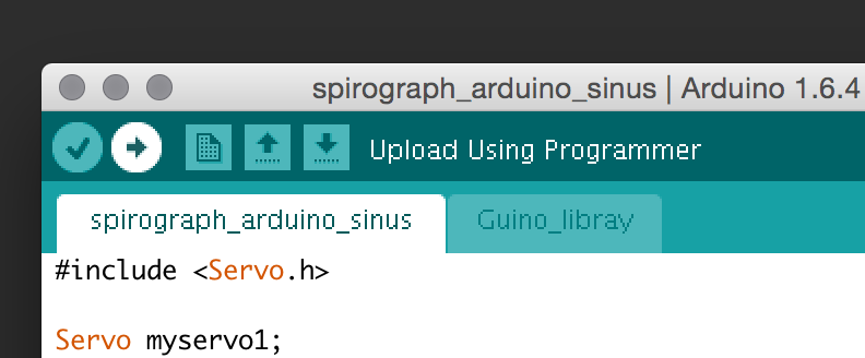
The arduino board should blink and start to upload the code. When you have uploaded the code you can use Guino to control it. A general description on how to upload code can be found here.
GUINO:
We are using guino (you do not need to install from the link - everything is included in the ressource link above) to control the servos.
Through the Guino interface you can control the speed of the motors (the Guino is included in the ressource file above). Included are two sketches one with basic speed control and one where the speed is modulated by a sine wave to create more messy patterns.

Run the Guino app, choose the serial port, press connect. This should bring up the interface. Press the Pause toggle button to start the motors.


CAD Design software
The actual pdf file has been made with a yet-to-be-released software that automatically generates all the holes and edges. The software will soon be released. If you are interested a pre-release can be obtained by writing to (fablab@ruc.dk). The specific code of the design is the following:
void setupElements()
{

  setupMFab();

  canvas.x = 3;
  canvas.y = 3;

  canvas.popSpacing = canvas.toGrid(0.5f); // temporary change of popSpacing to make sure the baseplate sticks.
  mfab base = canvas.addRectPiece(0, 10, canvas.toGrid(337), canvas.toGrid(210)+18, "Base");
  canvas.popSpacing = canvas.toGrid(0.2f);
  base.addMountHoleRect(2, 2, 70, 16);

  mfab washer1 = canvas.addPopCirclePiece(86, 24, 5, "Washer");
  washer1.addCircle(2.5, 2.5, canvas.toGrid(4));

  mfab washer2 = canvas.addPopCirclePiece(92, 24, 5, "Washer");
  washer2.addCircle(2.5, 2.5, canvas.toGrid(4));

  mfab box = generateInsetBox(0, 82, 71, canvas.toGrid(35), 17, canvas);
  box.remove(1);


  // move the box sides around

  box.child(1).x = 73;
  box.child(1).y = 18;
  box.child(2).x = 73;
  box.child(2).y = 0;
  box.child(4).x = 0;
  box.child(4).y = 33;

  //Add servo holes in the box.
  for (int i = 0; i < 10; i++)
  {
    mfab servo = box.children.get(0).addServoHole(9+i*6.5, 4);
    servo.rotation =90;
  }

  mfab arm = canvas.addRectPiece(85, 10, 6, 12, "arm 1");
  arm.addServoMount(3, 2);
  makeholes(arm, 3, 5, 4);

  mfab arm2 = canvas.addRectPiece(92, 10, 6, 12, "arm 2");
  arm2.addServoMount(3, 2);
  makeholes(arm2, 3, 5, 4);

  mfab arm3 = canvas.addRectPiece(85, 35, 3, 26, "arm 3");
  makeholes(arm3, 1.5, 2, 12);

  mfab arm4 = canvas.addRectPiece(92, 35, 6, 30, "arm 4");
  makeholes(arm4, 3, 2, 12);

  arm4.addCircle(3, 28, canvas.toGrid(9.8));

  mfab arm5 = canvas.addRectPiece(85, 70, 3, 26, "arm 5");
  makeholes(arm5, 1.5, 2, 12);


  mfab arm6 = canvas.addRectPiece(85, 98, 3, 26, "arm 6");
  makeholes(arm6, 1.5, 2, 12);
  mfab arm7 = canvas.addRectPiece(90, 70, 3, 60, "arm 7");
  makeholes(arm7, 1.5, 2, 29);

  mfab arm8 = canvas.addRectPiece(95, 70, 3, 60, "arm 8");
  makeholes(arm8, 1.5, 2, 29);

  listMethods(canvas);
}