Make your own PCB with a CNC

There are multiple ways to create a PCB. This toturial takes you through the steps of using a CNC to mill a raw PCB plate into the circuit used for e.g. an arduino shield.
Download a template for an Arduino shield here.
Make contour paths in Corel Draw
 Multiple programs exists to route the circuit. In the end it needs to be edited in Corel Draw to make the contour paths (see other toturials on the learning page).
When done export the file as a PLT file.
Setup the CNC
Make sure to use an 0.8mm drill bit:

Use the Machine Wrench to change the drill bit:

Remember that the PCB should be level on the plate. Since the PCB is relatively thin the difference between "engraving and cutting becomes a matter of half milimeters. Use a piece of plywood and use washers to hold the PCB onto the board.

Load the PLT file into WinPC-NC.

Manually move the CNC to your zero-point location.


This should be the bottom left corner of the PCB - in which the drill should almost be touching the PCB.

Set this position as zero-point XYZ.

This should create a red mark in the corner of your drawing:

Then setup the cutting depths of the individual layers:

Set the layers that needs to be cut all the way through to 1mm and one repition. Set the layers that only should engrave to 0.20mm and zero repition:

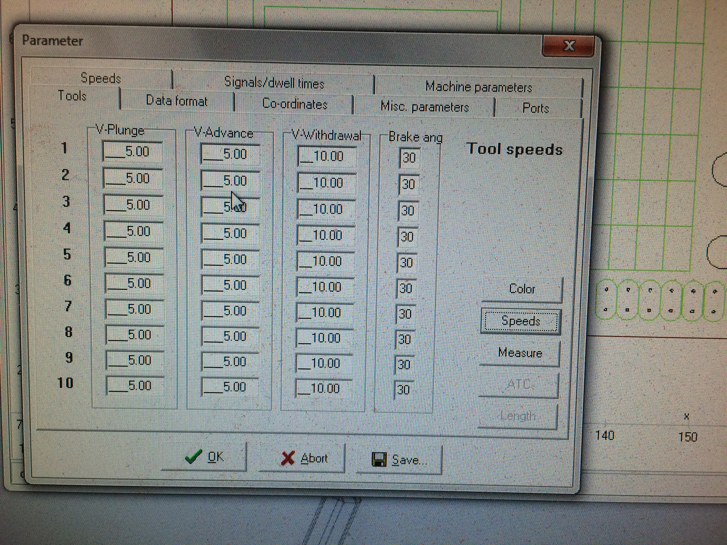
Set the speed to 5:
Make sure to cut the different layers one at the time. The last layer should be the one that cuts the outer path of the board - consequently seperating the cut PCB from the overall board.
Run the CNC machine: