CNC milling [Large]
CNC machine for lightweight materials such as plywood, wood, MDF, plastics, nylon, aluminium.
RaptorX-SL1200/S20 with 1200 x 2010mm working area. Remember to leave at least 10mm material around the edge and between larger parts. The Z axis has max 110mm travel, which may be reduced by tool length and material thickness. Normally mounted with a Kress 20.000 RPM spindle carrying a 3mm mill, can be equipped with 1-5 mm mills or a plasma cutter. Precision under 0.1 mm.
Practically, the only process we recommend as being easy is cutting max 12mm wood with a 3mm radius mill. This is what we do as standard 90% of the time, and the process we recommend as being not terribly painful. It is possible to cut thicker things, but requires changing to a bigger, thicker tool, so is slower, noisier and you cannot do small details.
FUSION 360
The machine is able to run G-Code written by Fusion.
When making parts in Fusion there is three important things there is important for the machine.
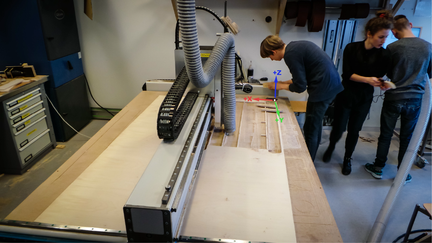
1. make the setup and setting the coordinate system right (see picture above for machine coordinate system
2. Using tools we have. Download the tool library here.
3. Use the right post-processer for exporting G-Code (Mach3Mill)
Guide for 2D geometry
Guide to using the large scale CNC machines for 2½ D (flat-ish) milling - the Raptor at FabLab RUC and the Giant Open Source CNC at Illutron.
The workflow is almost the same on the two machines. Lines starting with Raptor: or GOSC: indicate something specific to that particular machine. We may fork the guide into two at some point in the future (or more likely, they may get more similar, if we replace the specially skinned Mach3 on the Raptor with the standard Mach3 look).
This guide describes how to use Corel Draw (or another 2D vector drawing program such as Inkscape, Illustrator, AutoCAD etc.), LazyCAM and Mach3 to mill 2D-ish things out of large sheets of material such as plywood, OSB, HDF, MDF, plastic etc.
This guide does not cover 3D milling, for which we use a 3D drawing program such as tinkercad, Fusion 360, (123Design has stopped working), AutoCAD, Rhino, Solidworks, Inventor and plan the job and convert to G-code in MeshCAM or CamBam (or inside Fusion 360). If you want to get going with a new 3D program, we recommend (as of 9/2014).
TinkerCAD for newbies
Fusion 360 for experts (and it includes the CAM step).
The process is divided into 3 steps, which use 3 different programs. This is normal (although some setups have tighter integration between the programs than we do).
- CAD (computer aided design): Drawing is made in Corel Draw, and radius compensation is done. Radius compensation is drawing all lines 1.5 mm outside (or inside, for holes) where you actually want the cut, to take account of the milling head removing 3 mm of material. The result of the CAD stage is a drawing, in HPGL or DXF format.
- CAM (computer aided manufacturing): The cutting job is planned in the CAM program - things like how deep to cut, at what speed, how many times, in what order, in what direction etc. This is done in the program LazyCAM. The result of the CAM stage is G-code (.tap) - instructions telling the CNC machine control program (Mach3) exactly how to move the machine.
- Machine control: The CNC machines cutting head must be moved to allow the material to be put in and clamped, and the workpiece zero must be found (the zero point for the x, y and z axis - normally the top of the wood (z), near the corner (x,y). The machine control program then “plays” the G-code, moving the cutting head in the manner planned in the CAM stage. The machine control program we use is Mach3.
1. Drawing and radius compensation in Corel Draw
Note: the following is for if you want to make something an exact size and fit. If you just want to make art and don’t care that everything will be 1.5 mm smaller than you drew it, just save a DXF or HPGL file and skip straight to step number 2: LazyCAM. In either case, leave at least 6-10 mm between objects, and at least 10-12 mm to the edge (you need room for the screws to fix the material!).
- Open Corel Draw (Corel Draw costs money, one can download a month free trial version. Any vector drawing program can be used if you are willing to manually draw things 1.5 mm inside/outside where you actually want them. (Inkscape is free and Open Source and has a contour/offset function which is almost good enough, and probably will be good enough soon). You can perfectly well use Inkscape or Illustrator if you are happy placing lines by yourself by hand 1.5 mm beside where you want the actual cut.
- Draw or import something. (import tip: older versions of .dxf, .ai work best) (tip: it is usually a good idea to draw a box the size of your material, e.g. 2440x1220mm, so you can see how your parts fit. Delete this box before exporting) (general vector drawing tip: use shaping tab (weld and trim) to add and subtract shapes from each other. (corel draw nudge tip: nudge distance defaults to 2.54 mm - make life easier for yourself by changing it to 1 mm, super nudge 10mm, micro nudge 0.1 mm - then you can use the arrow keys, ctrl+arrow and shift+arrow to move things effectively. Change this setting in tools->customisation->document->rulers).
- Make sure that all the curves are closed and objects with holes in are combined (Arrange->combine) (grouping is not enough) - they must have an inside and an outside. Test by filling with a colour. If you see a colour filled shape with holes in it, all is well. If you see a shape filled, and with other shapes just lying on top of it or hidden underneath it, radius compensation will not work (there is no inside and outside, just one object on top of another object).
- Radius compensate using the contour function (see fig. 1 below). If you cannot see the Contour tab, someone has closed it - get it back with windows->dockers->contour (see fig. 2 below) Choose
Outside (usually - sometimes Inside in some special cases e.g you are doing a hole on its own),
- 1,5 mm (if using a 3 mm mill, 2,5 mm if using a 5 mm mill, 3 mm if using a 6 mm mill etc.)
- 1 step.
- It is easier to see what you are doing if you choose a different colour (click the second of the strange looking icons at the top of the contour window).
- Advanced tip: if you want to make a pocket - a recess (not a hole that goes all the way through) sculpted out of the material - this can be achieved with the same contour function, but using 100 steps (it will just draw as many lines as there is space for). To use the contour function on multiple objects at once you must group (Arrange->group) the objects first.
- Break the contour apart from the original line using Arrange->Break contour group apart (see fig. 3). Then you can copy the contour - or delete the original line. Select the parts you want actually cut (leaving out the original lines)
- Export to HPGL (.plt) Check “selected only” and “skip dialogue” (if you forget, the dialogue will just ask you which colour pens to use - just click ok, it doesn’t matter. If you are working on a different computer to the one connected to the CNC machine, copy both the HPGL and the Corel Draw file to a USB key to move the files to the CNC machine computer (which is not on the internet).
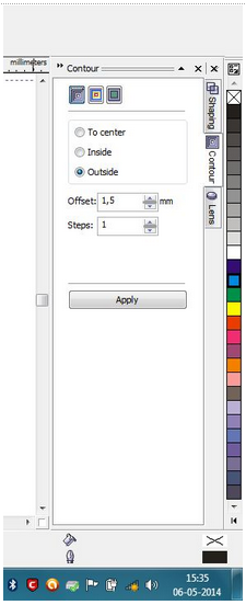 Fig 1
Fig 1
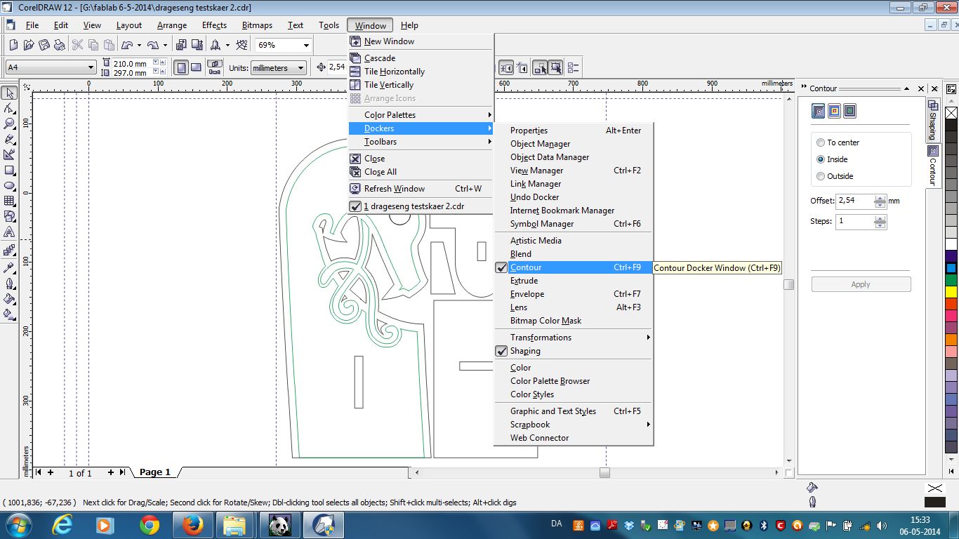 Fig. 2
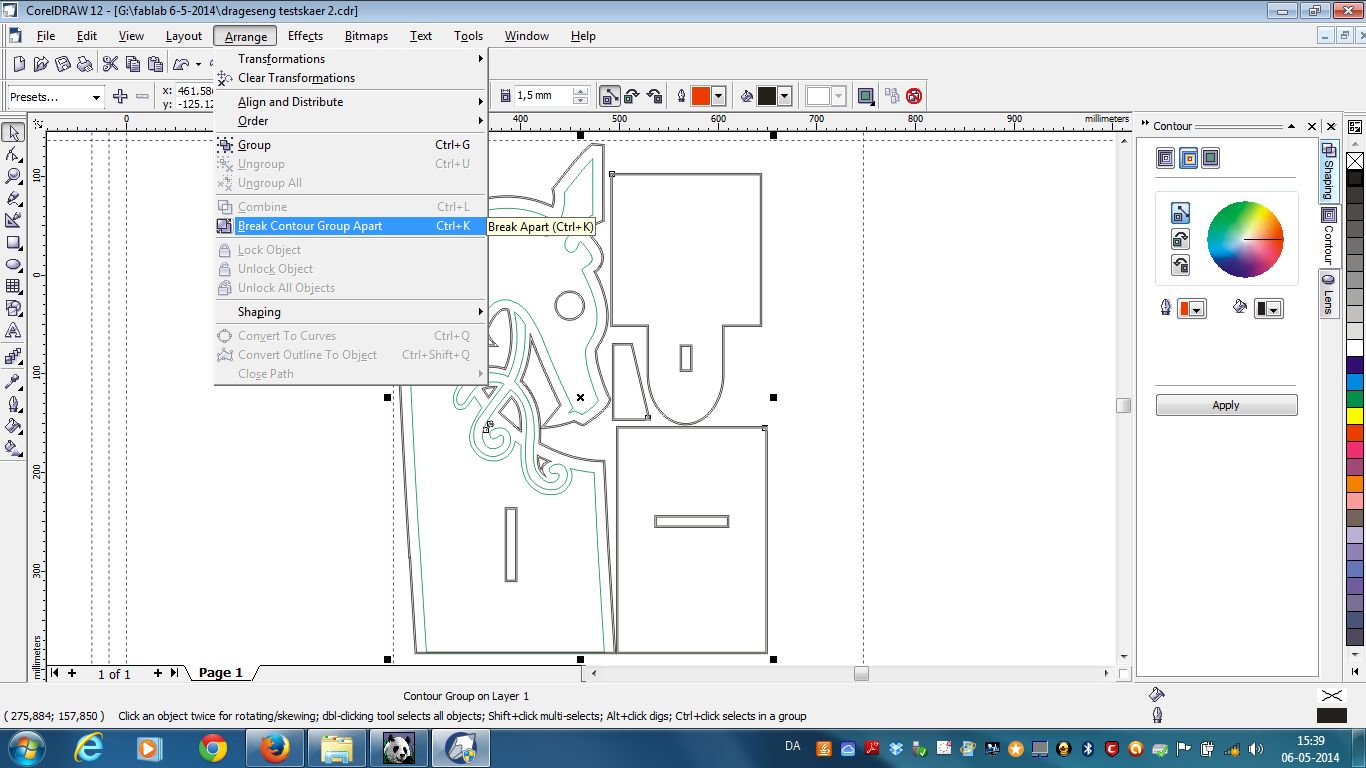 Fig. 3
2. LazyCAM - planning the cutting job
Please copy your file to the computer (doing things from the USB stick is just less reliable, and you will forget your USB stick) and put it in the “Documents” folder (not on the desktop). If your file is secret and may not be published as part of a guide or example of a good project, please start all filenames with secret-
- Open LazyCAM (LazyCAM is free for download. It is in Beta and is discontinued. There are therefore user interface quirks that will never be fixed. But it is free and works). Press the Open .dxf button (Fig. 4) (Open DXF actually means open any kind of vector file).
- Change the type to HPGL in the open file dialogue if it is a HPGL file you are opening (if it is a dxf just leave it as dxf).
Open your file.
Press “MILL” (Fig. 5) (you are milling, not turning = lathe = drejebænk) - Press “MM” (Fig. 5) (if the file is in millimeters)
Press "reset origin" (Fig. 5) in the right pane - this moves the 0,0 to a sane place - the lower left corner of your drawing, instead of whatever random place it was before in your file.
Press “relayer” in the right pane - this changes the cut order so all inner things are cut first and the outer edges last. This is necessary if you have any inner things (holes, for example). If you don’t have any holes in things, you can skip this step. - For advanced jobs only: If you need to relayer manually (this is for advanced users only, and is only necessary if e.g. you need some things cut only 6mm deep, and other things cut 13 mm deep - you need to note the buttons on the right - “zoom box” “select box” “select single/multiple”. Click on the chains you want treated differently (you can click on them either in the drawing on the right or in the list of chains on the left), right click and choose “send to layer” (if you already have a suitable layer defined for the desired work process) or “send to new layer” (if you want to make a new layer for this work process). You can also select a chain in the left side list of chains and drag it to a different layer.
- Click on a layer - for example “Inside”. (Fig. 6) Click on the “tool” button in the middle bottom pane. Select a suitable tool (Fig. 7) - usually 3 mm diameter, 1000 mm/min speed for precision or 2000 mm/min for speed, cut depth per pass should be max 7 mm and max ⅔ of the thickness of the material if you want it to be pretty and precise. If you change any numbers in the tool dialogue, remember to click “update tool” or it will not be saved. If you just want speed, it can be up to 12 mm and the whole depth of the material. Example: 12 mm ply pretty: cut depth per pass 7 mm: first it will cut to 7 mm depth on the first pass. On the second pass it will cut the rest. Example: 6 mm mdf fast: set cut depth to 9 mm per pass. It will cut in one go, and the entry and exit may be ugly and need sandpapering.
- Click “send to all layers” - remember this! Otherwise there will be layers with no tool set, this will result in the machine moving at a snail’s pace and you will have to start over.
- Click on some other layer or chain.
- Click on a layer - for example “Inside”. Set rapid height to 10 mm - important - the height the tool should be above the workpiece when making moves between cuts. If you know what you are doing and need speed, you could set it lower, for example to 6 mm - it depends whether the machine and your material is really flat.
- Set the cut depth - this should be 1-2 mm thicker than the material. E.g. you have 12 mm plywood - the cut depth should be -13 or -14 (american keyboard, the + is the minus) If you forget the - , the machine will “cut” 13 mm up in the air - no disaster, but no result either.
- Click set layer.
- Click set all layers.
- Those choose the tool, “send to all layers”, “rapid height 10 mm”, “cut depth -13 mm”, “set layer”, “set all layers” steps are so important you must check you remembered them all. Do this by:
- Click on some other layer or chain.
- Click on the uppermost layer (for example “Inside1”) and see that it in the middle bottom pane has a tool, rapid 10 mm and cut depth -13.
- Click on the next layer (for example “Inside2” or “Outside”) and check the same.
- Continue until you have checked all layers (there are usually only 2 to 4). But if you got it wrong, you would have to regenerate the G-code file and start the cutting job over from the beginning, which wastes a lot of time.
- Click “post gcode” - just click ok to the options it asks about - the file is put (by default) in C:\Mach3\Gcode - do not change this. (possible error: the “post processor” should be set to “Mach3”, not “generic G-code” (it will be correct by default unless someone changed it). If it is set to “generic G-code”, the job will work in Mach3 EXCEPT the spindle will not start - which means either you have to really quickly start it manually by clicking the “Spindle CW” button in Mach3 after starting the job, or the cutter will break (which is a waste of 45 kr, but not a major disaster).
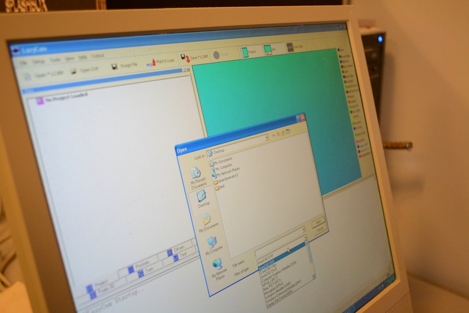 Fig. 4
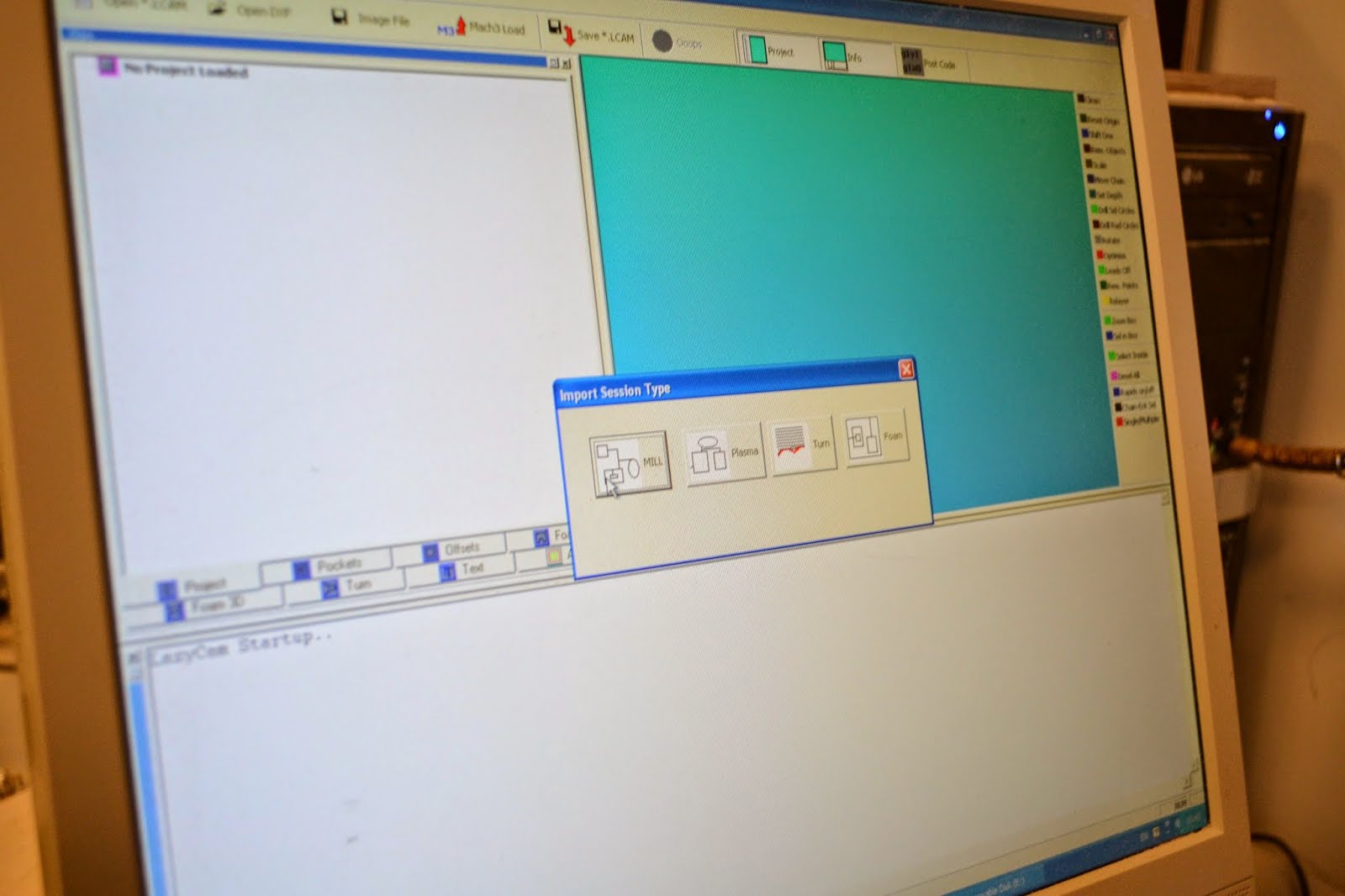 Fig. 5
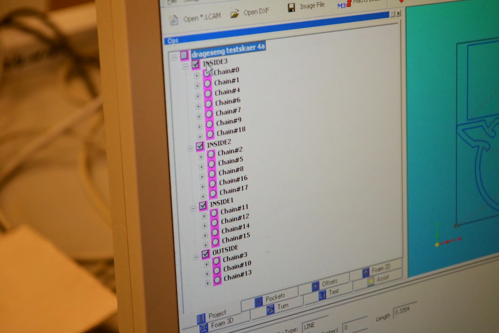 Fig. 6
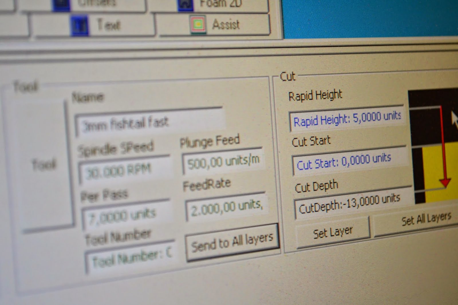 Fig. 7
3. Mach3 - setting zero point and controlling the CNC machine
Start Mach3 - click on the icon on the desktop with the appropriate name, it will start Mach3 with the right settings for the particular CNC machine. Mach3 costs (a bit of) money and is used for all hobby and semipro CNC machines. The only real alternative to it is LinuxCNC (or the dedicated controllers on high end professional CNC machines).
Raptor specific: Select which setup in the dialogue after the program starts - use the one called “use me”
Both machines:
Choose File->Load gcode
Fix the material in the machine. Put the screws as close to the edge as possible. Make sure the middle of the material is not bowing upwards (if it is, the easiest way of fixing that is to turn the material the other side up, so the middle tries to bow downwards, which it can’t because of the table).
Now the guide diverges between the Raptor and the GOSC as the Raptor has a special custom skin for Mach3.
Raptor specific:
- Press the hand icon (to get into manual control mode) (Fig. 8)
- Press the big red start/stop button to energise the xyz motors.
- Press “referenz fahrt” (WARNING the machine will now move to find its reference end switches on all three axises - x,y, and z) (Fig. 9). The machine coordinates should now read 0.00 on all three axises.
- Click on the X, Y, Z arrows on the screen OR use the arrow keys on the computer keyboard to move the cutter from the machine zero to the workpiece zero - which should be the bottom left corner of (X,Y) the material to be cut (or where ever on the material you want the job to start), just touching the top surface (Z). If you press shift on the computer keyboard, the machine will move at double speed (use caution - especially on the Z axis, where you can collide with the workpiece). (It can be a good idea to make a mark on the material at the XY zero, then you can find it again and restart the job without wasting all the material if something should go really wrong such as a power failure or computer crash). Press the three buttons X0, Y0 and Z0 to zero the workpiece coordinate system at the cutter’s present position. The workpiece coordinates should now read 0.00 on all three axises.
- Make sure that the ventilation is on and sucking air.
- Click on the strange icon that is supposed to look like a tool bit, to leave manual control mode and enter automatic control mode.
- Check you are on line one of the G-code file. Otherwise press |<< to rewind.
- Press the button with the green 1 with four arrows around it to start the job.
- Wear ear and eye protection.
- Enjoy.
GOSC specific:
- Press the big red start/stop button to energise the xyz motors.
- Press “reference all” vertical button next to the XYZ readout (WARNING the machine will now move to find its reference end switches on all three axises - x,y, and z). The machine coordinates should now read 0.00 on all three axises. If the machine refuses to move or move far enough you may need to click on the “software limits” button to turn off the safety features that prevent the machine moving further than Mach3 thinks it can (if Mach3 has a strange idea about where the machine is). Use the arrow keys on the computer keyboard to move the cutter from the machine zero to the workpiece zero - which should be the bottom left corner of (X,Y) the material to be cut (or where ever on the material you want the job to start), just touching the top surface (Z). If you press shift on the computer keyboard, the machine will move at double speed (use caution - especially on the Z axis, where you can collide with the workpiece). You must know to use the arrow keys on the computer keyboard - there are no buttons on the screen that can move the CNC machine. (It can be a good idea to make a mark on the material at the XY zero, then you can find it again and restart the job without wasting all the material if something should go really wrong such as a power failure or computer crash).
- Press the three buttons X0, Y0 and Z0 to zero the workpiece coordinate system at the cutter’s present position. The workpiece coordinates should now read 0.00 on all three axises.
Make sure that the ventilation is on and sucking air.
Check you are on line one of the G-code file. Otherwise press “rewind” to rewind. - Test that the spindle can actually start by pressing the “Spindle CW” button. Press it again to stop the spindle again (just do this for the first job of the day).
- Press “Cycle start” to start the job.
- Enjoy. Wear ear and eye protection.
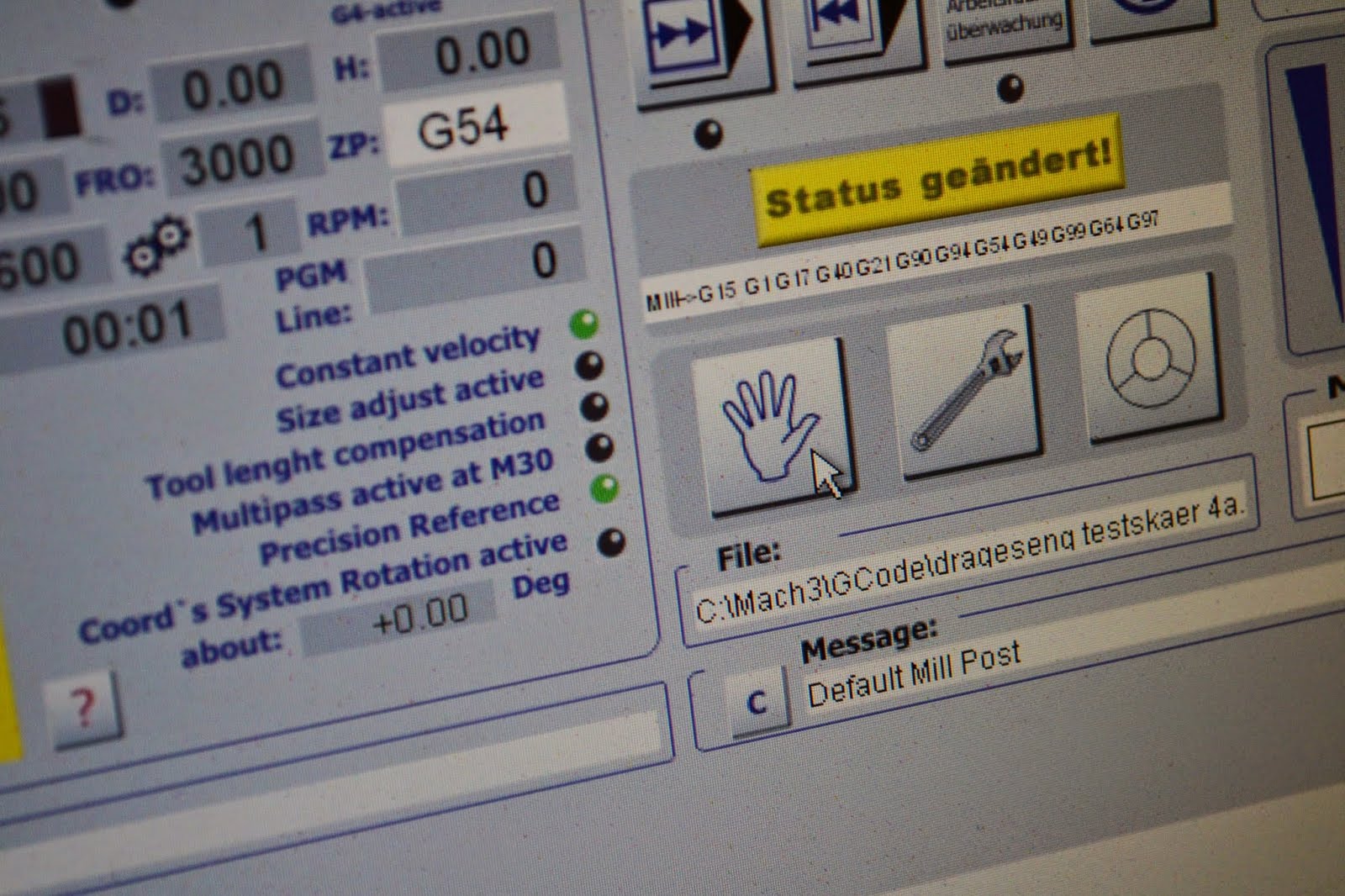 Fig. 8
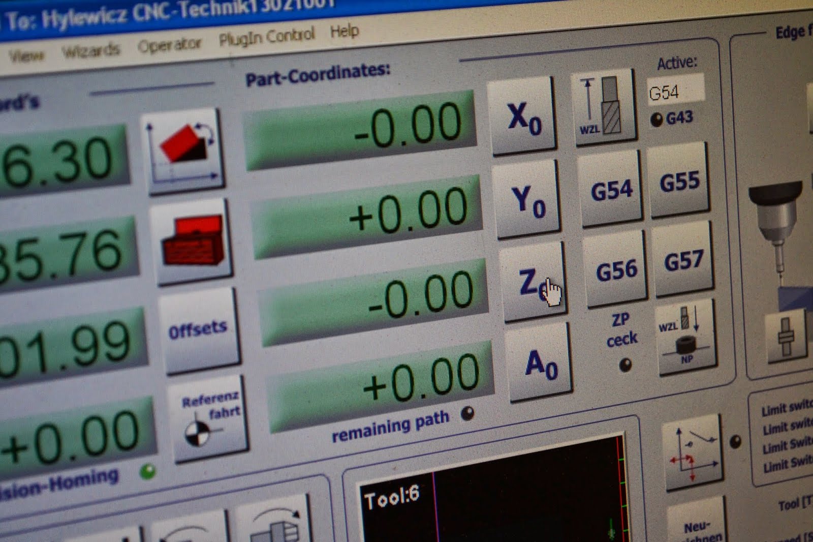 Fig. 9
Other processes: Changing the cutting tool
There is a special set of three spanners hanging on/by the CNC machine. They are 13mm ground specially thin, 14mm and 17mm.
Procedure is as normal for a mill, but use the specially thin 13mm wrench as a lever to force the cone formed collet out - if you do not have this special tool it is very difficult to get the cone formed collet out without dismounting the whole spindle from the machine and doing violence on it in a vice (in danish=skruestik).
There is a small black plastic button on the side of the spindle which locks the spindle for loosening and tightening, but this button is not very robust, which is why the 14mm wrench is there - it may be better to use the wrench on the actual spindle itself than count on the little black plastic button surviving long.