Introduction to Arduino
Arduino is an open-source electronics platform that is used to sense the real world, make interactive projects and prototypes.
Download the Arduino software here: Arduino. This is used to program the Arduino microcontroller (also known as a board). Thereafter, the program is in the Arduino, and will continue to run without the computer present.
First, test that you can connect to the board and make it run a simple program. Connect it to a USB port on the computer. Open an example program by clicking File -> Examples -> 01.Basics -> Blink. Click the right-pointing arrow at the menu or press Ctrl+U to upload the program. After a few seconds and a bit of blinking, you should see an LED on the board blinking steadily on/off every two seconds. The program is stored on the board, and starts when powered up, it will blink on any USB power supply.
If you get an error message when uploading, go to Tools -> port, select a different port and try again a few times. You may also have to try different USB ports on the computer.
When the program is working, use File -> Save As to save it under a different name. Then change the blink timing, by changing the numbers where it says delay(1000); Upload the new program, check the effects. You are now in control.
It's often very practical to show data from the board on the computer. Open File -> Examples -> 01.Basics -> ReadAnalogVoltage. Upload the program. Open Tools -> Serial Monitor. You should now see a stream of numbers scrolling. The numbers show electronic noise measured by the board. You can get a plot of the data by opening Tools -> Serial Plotter (The Serial Monitor window must be closed first). Try touching the board, or maybe put a wire in the plug marked A0. Save a copy of the program, and add a new line beneath the line Serial.println(voltage); saying
Serial.println("BlahBlah");
Upload, open the Serial Monitor, check effect.
If you can't get the Serial Monitor/Plotter to work, change the "baud" number. Try 9600 or 115200. It should match the line in the program saying Serial.begin(9600);
You are now ready to connect electronics to the Arduino, and program it to control them!
Control neopixels
The Arduino board is able to read inputs and write outputs. In this example, the input will be a potentiometer (a variable resistor) and the output a string of neo-pixels - individually controllable light emitting diodes. Using code, we can control how the input affects the output.
Neopixels are versatile light strips where each diode can be controlled individually. Each diode or pixel has red, green, and blue - each can be from 0 to 255 in brightness. Multiple libraries exist to more easily control neopixels. We suggest you use "Fastled".
Add the library: "menu->sketch->include library->manage libraries"

Search for "fastled" and click install

Use this wiring:

IMPORTANT: Disconnect the Arduino from power, and connectthe wire labelled 5v on the Neopixel string to 5V on the Arduino, D0 (neopixel end) to digital Pin 4 (Ardunio end) and G (neopixel end) to GND (Arduino end). If you are soldering your own, make sure to connect to the neopixel Din, not Dout - see the arrow:
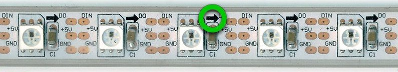
Note the wires we have soldered on are not always the same colours.
This example sketch will turn the first three pixels red, green and blue:
  #include "FastLED.h"

  // How many leds in your strip?
  #define NUM_LEDS 10
  #define DATA_PIN 4


  // Define the array of leds
  CRGB leds[NUM_LEDS];

  void setup() {
          FastLED.addLeds<NEOPIXEL, DATA_PIN>(leds, NUM_LEDS);
  }

  void loop() {
    // Turn the LED on, then pause
    leds[0]= CRGB( 255, 0, 0);
    leds[1]= CRGB( 0, 255, 0);
    leds[2]= CRGB( 0, 0, 255);
    FastLED.show();

  }
Exercise: #1 Try to change colors and turn more lights on.
Adding an input - potentiometer
A potentiometer is a "volume knob" - a variable resistance, which we can read into the Arduino board as an analog value (read more here)
Use this wiring:

Left pin = black wire to GND on Arduino,
Middle pin = white or yellow wire to A0 on Arduino
Right pin = red wire to 3.3V on Arduino.
(We only use the 3.3V pin as we have already used the 5V pin for the neopixels - if we had a breadboard or circuit board involved it would be normal to split the 5V and power both with 5V).
In the following code we will let the potentiometer control the brightness of the first pixel.
#include "FastLED.h"

// How many leds in your strip?
#define NUM_LEDS 10
#define DATA_PIN 4

// Select the input pin for the potentiometer
int potPin = A0;

// Variable to store the value coming from the sensor
int val;
int bright;


// Define the array of leds
CRGB leds[NUM_LEDS];

void setup() {
  FastLED.addLeds<NEOPIXEL, DATA_PIN>(leds, NUM_LEDS);
}

void loop() {

  val = analogRead(potPin);
  bright = map(val, 0,684,0,255);

  leds[0] = CRGB( bright, 0, 0);
  leds[1] = CRGB( 0, 255, 0);
  leds[2] = CRGB( 0, 0, 255);
  FastLED.show();

}
Now we have defined the input pin and two variables. The int val will hold the values returned by analogRead(). This function reads the values coming in from the potentiometer going from 0 to 684 (when connected to 3.3V) and 0 to 1024 when connected to 5V.
int bright is used to define the brightness the first pixel. To do so, the function map() is used to re-map the range of values from the potentiometer to the range of values (0-684) used to define the brightness of a neo-pixel (0-255):
Exercise #2 Let the input from the potentiometer control more pixels.
Making a chase
#include "FastLED.h"

// How many leds in your strip?
#define NUM_LEDS 10
#define DATA_PIN 4

// Select the input pin for the potentiometer
int potPin = A0;

// Variable to store the value coming from the sensor
int val;
int brigth;
int ledsOn;


// Define the array of leds
CRGB leds[NUM_LEDS];

void setup() {
  FastLED.addLeds<NEOPIXEL, DATA_PIN>(leds, NUM_LEDS);
}

void loop() {

  val = analogRead(potPin);
  //brigth = map(val, 0, 684, 0, 254);
  ledsOn = map(val, 0, 684, 0, NUM_LEDS);

  //turn all pixels off
  for (int i = 0; i < NUM_LEDS; i = i + 1)
  {
    leds[i] = CRGB( 0, 0, 0);
  }

  //Turn the pixels on according to input from potentiometer
  for (int i = 0; i < ledsOn; i = i + 1)
  {
    leds[i] = CRGB( 255, 0, 0);
  }
  FastLED.show();

}
This time we are using two for-loops. The first turns all the pixels off and the next turns on according to the input from the potentiometer. Without the first loop turning all off they would keep turned on when turning the potentiometer down. Note we are using the variable ledsOn to define how many times the loop should run.
Exercise #3 Change the code so there only is one pixel on at a time, and which one is on is controlled by the potentiometer.
Possible solutions
Exercise #3
#include "FastLED.h"

// How many leds in your strip?
#define NUM_LEDS 10
#define DATA_PIN 4

// Select the input pin for the potentiometer
int potPin = A0;

// Variable to store the value coming from the sensor
int val;
int brigth;
int ledsOn;
int chase;


// Define the array of leds
CRGB leds[NUM_LEDS];

void setup() {
  FastLED.addLeds<NEOPIXEL, DATA_PIN>(leds, NUM_LEDS);
}

void loop() {

  val = analogRead(potPin);
  brigth = map(val, 0, 684, 0, 254);
  ledsOn = map(val, 0, 684, 0, NUM_LEDS);
  chase = map(val, 0, 684, 0, NUM_LEDS);

  Serial.println(val);

  //turn all pixels off
  for (int i = 0; i < NUM_LEDS; i = i + 1)
  {
    leds[i] = CRGB( 0, 0, 0);
  }

  //Turn the pixels on according to input from potentiometer
    leds[chase] = CRGB( 255, 0, 0);

  FastLED.show();

}